Understanding what a DC linear actuator is helps you make an informed decision for your application. As a supplier, we know that selecting the right component is crucial for the performance and reliability of your project. This article explains the fundamental principles of how these devices function. This knowledge empowers you to specify the correct actuator for your needs.
Electric Motor Movement
A DC linear actuator fundamentally begins its operation with an electric motor powered by direct current. This motor generates rotational force, which is the primary source of movement for the entire device. The use of DC power is common due to its compatibility with batteries and simple control systems, making these actuators suitable for mobile and low-voltage applications. To transform this rotary motion into a straight line, or linear, motion, an internal mechanism is required. This is typically achieved through a lead screw or a gearbox assembly that efficiently converts the spinning action of the motor’s shaft. The controlled nature of this conversion allows for precise positioning and repeatable movement, which is essential in many automated tasks. For more detailed information on the components of a dc linear actuator, you can consult technical resources that explain the interplay between the motor and the mechanical transmission inside the unit.
Linear Motion Device
The core function of this device is to provide controlled linear motion, which is a push or pull action in a straight line. This is distinct from the rotational motion of a standard motor and is necessary for applications requiring lifting, lowering, sliding, or tilting. The mechanism inside, often a screw that travels through a nut, is responsible for this precise conversion of motion. The design ensures that the force generated by the motor is effectively translated into linear force, known as thrust. This thrust capability determines how much weight the linear actuator can move. The entire assembly is usually housed within a protective casing, which safeguards the internal components from dust, debris, and other environmental factors that could affect its performance and lifespan. This makes the device a self-contained unit ready for integration into various systems.
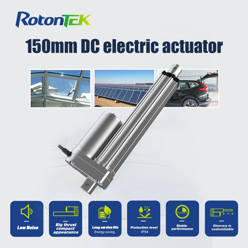
Rod Extension and Retraction
The most visible part of the actuator’s operation is the extension and retraction of a rod, often called the thrust tube. This rod is connected to the internal mechanism that converts the motor’s rotation. When the motor turns in one direction, the rod is pushed outward, extending from the main body of the actuator. When the motor’s direction is reversed, the rod is pulled back inward, retracting into the body. The distance the rod travels is known as the stroke length, a key specification for any application. The speed of this movement is generally determined by the motor’s RPM and the pitch of the lead screw. By electrically controlling the polarity of the DC power supplied to the motor, users can precisely command the rod to extend, retract, or stop at any point within its stroke, enabling automated and repeatable linear positioning.
Conclusion
A DC linear actuator is a transformative component that brings automated, precise linear motion to countless applications. Its value lies in its electromechanical simplicity, controllability, and adaptability across diverse industries. Whether for an industrial machine or a consumer product, selecting a well-engineered actuator is crucial for system integrity and user satisfaction. For those seeking reliable motion solutions backed by direct engineering support, we invite you to explore the specifications and capabilities available through Rotontek.