Electric motor efficiency is a critical aspect for businesses aiming to optimize performance and reduce operational costs. Various factors affect the overall efficiency of electric motors, particularly in applications that rely on advanced technologies like motor transaxles. Understanding these factors can help organizations enhance their operational capabilities.
Design and Construction of the Motor
The design and materials used in electric motors play a significant role in determining their efficiency. Motors constructed with high-quality materials reduce energy losses associated with heat generation. For example, the choice of magnetic materials can influence energy consumption; efficient magnetic circuits minimize hysteresis losses, which directly affect electric motor efficiency. Additionally, the overall design, including rotor and stator configurations, impacts how effectively a motor can convert electrical energy into mechanical energy.
Another important factor is the type of windings used in the motor. Different winding configurations can lead to varying levels of efficiency, especially under load. By optimizing these design elements, manufacturers can significantly enhance motor performance while minimizing energy waste.
Impact of Operating Conditions
The operating environment of electric motors also heavily influences their efficiency. Factors such as temperature, humidity, and load conditions can affect performance. For instance, higher temperatures can lead to increased resistance, thus reducing motor efficiency. Ensuring that motors operate within their ideal temperature range is crucial for maintaining performance.
Additionally, load variability can affect how effectively a motor operates. Motors that are consistently operated under load conditions that differ from their design specifications may experience reduced efficiency. Employing a motor transaxle can help maintain optimal performance by better matching motor output to real-time demands, which in turn maximizes electric motor efficiency.
Selecting the Right Components
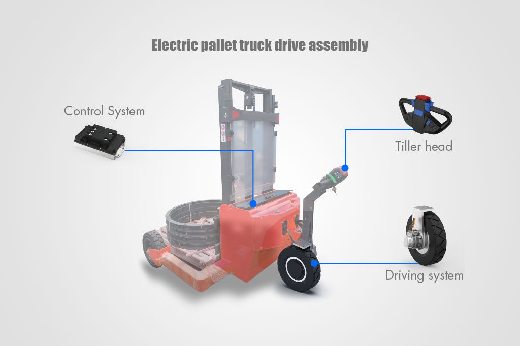
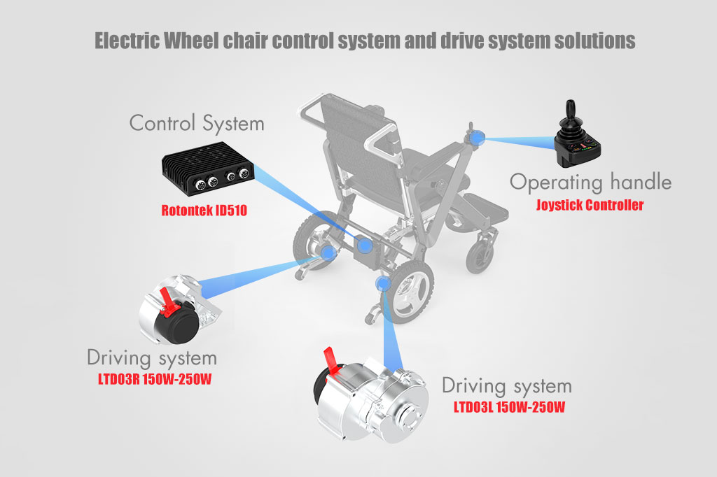
Choosing the right components, such as controllers and transaxles, can significantly impact the efficiency of electric motors. Utilizing advanced motor transaxle technologies ensures that the electric motor’s performance is optimized and tailored to specific applications. High-quality controllers allow for better monitoring and management of power, thereby enhancing overall system efficiency.
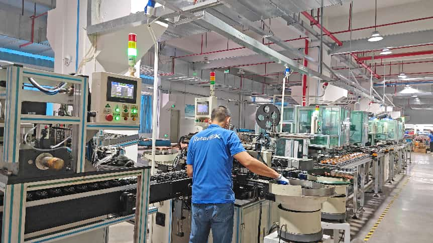
At Rotontek, our team of over 40 engineers, including former experts from Panasonic, focuses on creating customized motor solutions that cater to a diverse range of applications. Serving more than 40 countries across North America, South America, Europe, Australia, India, Vietnam, and beyond, we combine our expertise in AC electric motors with advanced transmission and transaxle technologies.
We are dedicated to delivering reliable, eco-friendly solutions, and we understand that optimizing electric motor efficiency is key to achieving your business goals. By partnering with Rotontek, you gain access to innovative motor designs and tailored solutions that enhance performance while reducing energy consumption. Together, we can drive efficiency in your operations and contribute to a more sustainable future.