Installation of electro hydraulic actuators requires careful attention to operating details.70% of equipment failures are caused by environmental issues so make sure it is installed with care in a clean, dry environment. Select an appropriate location that is optimal for the bracket. If a 10mm steel as the bracket makes it easier for you to be fixed tightly. During installation of the hydraulic pipeline, it is necessary to screw each connection manually using a torque wrench with set pressure in the system up to 150 bar. The final stage,fully testing and calibrating confirming every parameter is within limit.
Preliminary Preparation and Inspection
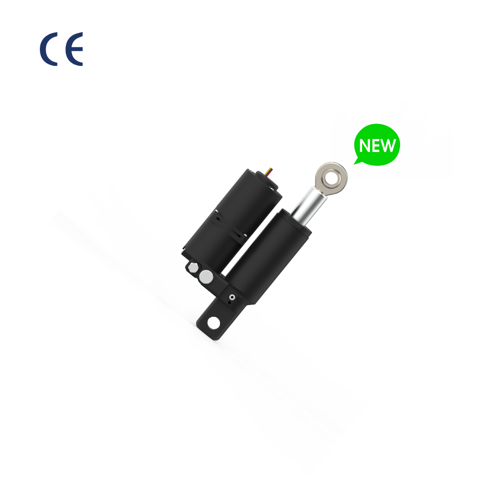
Installation of an electro hydraulic actuator is a work that can only be done after proper preparation and inspection. Therefore, make full preparations before installing the electro hydraulic actuator. First of all, before installing the electro hydraulic actuator, ensure that you have all the required tools and equipment. Based on previous experience, the lack of tools is one of the reasons for the delay in installation. Ensure that the model and specification of the electro hydraulic actuator you choose are in full compliance with the system requirements. For example, if you want an actuator that can meet a maximum pressure of 200 bar, then the lack of contradiction with this specification, the original electro hydraulic actuator is not suitable to cause system failure, the actuator can not achieve the expected performance.
The next step is to inspect the environment. Therefore, ensure the best environment and installation place. Generally speaking, the environment in which the equipment is installed must be dust-free and dry. In addition, the temperature and humidity in the place of work must satisfy the working requirements of the actuator. Secondly, the land should be flat without inclinations and no unstable areas on the ground. The level can be used to inspect because the actuator cannot be installed on an inclined surface. If the environment does not meet the requirements, some measures should be taken to improve it, such as dust covers and dehumidification equipment. Finally, inspecting the electro hydraulic actuator package and transportation. Specifically, confirm that the actuator has not been damaged during transportation and that all parts and accessories are included. Otherwise, contact the supplier and resolve it as soon as possible. At the same time, all inspection results should be recorded for reference in subsequent installations and maintenance work.
Bracket Installation and Fixing
To get started, it is essential to understand that the electro hydraulic actuator bracket is to be properly installed. Its exact position is to be determined with regard to the installation standards. Generally, the choice and the quality of installation of the bracket affect the actuator’s life cycle and efficiency of operation. For instance, the use of the 10mm thick steel plate bracket was necessary to guarantee the bracket’s stability and load-bearing capacity. Choosing a thinner bracket may cause deformation or bracket rupture.
Furthermore, the bracket is to be carefully calibrated using the level. In this case, the horizontal error should not exceed ±0.1 degrees. It is so because even the minimal slant causes the unsteady operation and mounting of the unit that contributes to the wear. Following calibration, the bracket is to be bolted using the high-strength bolts. All bolt or other connection points are to be securely fastened. It is noteworthy that the tightening torque for the bolts is to be adjusted carefully regarding the manufacturer’s recommendations in order to achieve a maximum level of tightening without the damage to the bolts or the threading.
Finally, the bracket stability and that of the foundation are to be confirmed. Check the foundation to ensure it may bear the whole weight of the actuator and the bracket and to confirm that it will not vibrate and operate under the influence of gravity causing them to move. If necessary, add the vibration pads or the reinforcement materials.

Hydraulic Line Connections
For the normal operation of the electro hydraulic actuator, the connection of the hydraulic system is the foundation. The electro hydraulic actuator requirements for hydraulic connection are as follows. According to the hydraulic circuit diagram of the electro hydraulic actuator, connect the hydraulic pipelines respectively. It is recommended to use a high-pressure oil pipe with a diameter of 16 mm. It can ensure the stability of the hydraulic fluid and avoid the phenomenon of insufficient flow or pressure loss caused by a small diameter of the pipe. Tighten all hydraulic connections with a torque wrench, and the specification is screwed. The oil pressure of the start-up accumulator group is 150 bar, so the system pressure should be adjusted to 150 bar to ensure that the actuator can be used normally under the situation of the maximum load.
Before connecting the hydraulic pipeline, it is necessary to ensure that the hydraulic pipeline and all the joints should be clean and free of impurities. Special cleaning agents and tools should be used during the cleaning process to avoid contaminating the hydraulic system. When connecting the hydraulic pipeline, attention should be paid to the bending radius and the way of laying of the piping. No joints should have too small of a bending radius or be twisted. The bending radius is limited too small, which will increase the internal flow resistance and accelerate the wear of the hydraulic oil. After connecting the hydraulic system, the initial pressure should be tested. Then, gradually increase the pressure, and check whether there are oil or oil leakage at all joints and tubing. Otherwise, shut it down immediately and troubleshoot it. According to the standard of hydraulics, each joint and pipeline should not be tested less than twice to ensure the airtightness and reliability of the system.
Electrical System Connection
Perform electrical connections according to electrical diagrams, all connections should be connected correctly. The power supply voltage should be 24V DC and during operation should not fluctuate more than ± 5%. Maintaining this parameter is very important for the normal operation of the actuator.
All electrical connections should be securely mounted to eliminate poor contact due to loosening. The grounding connection must be reliable in order to eliminate possible electrical hazards that may occur to the electro hydraulic actuator. Shielded cables should be used to connect the signal line, which will reduce the electromagnetic interference and, consequently, improve control accuracy. All cables and connectors should be carefully inspected, their quality characteristics should make them suitable for use in the described conditions. Moreover, the use of cables and connectors that meet industry standards allows to significantly improve the reliability and safety of the entire system. It is important to follow the wiring diagrams provided by the equipment manufacturer, including the correct connection of the power supply and signal transmission cables.
After connecting all the cables, you should perform the initial start of the power supply, and gradually increase the voltage while monitoring the operation of all connection points. If any anomalies are detected, such as instability of the voltage in the system or poor contact at some connection point, then the machine should be immediately turned off and inspected and repaired. According to generally accepted rules, each connection point should be powered on at least 2 times to ensure the system’s reliability and stability.
Testing and Adjustment

After the installation is complete, it is necessary to carry out comprehensive testing and adjustments. First of all, check whether the hydraulic system pressure is normal, the standard pressure is 150 bar, and gradually increase the load. According to the response of the actuator after being put into use, the debugging can be extended to 30 minutes. When adjusting the working parameters of the electro hydraulic actuator, such as pressure, speed, stroke, etc., it should be ensured that the actuator can work normally. Industry standards must also undergo no less than 5 full-stroke tests for each mounted actuator to ascertain that all parameters meet the standard.
During the debugging process, all parameters and pressure test results must be recorded. This data is very important for the follow-up maintenance and debugging. If you find that your machine has new problems during the test, such as instability of the pressure regulating valve, unstable speed, or fever of the hydraulic system, etc., shut down the machine immediately for maintenance. Each system parameter must be adjusted according to the actual situation to ensure that the system can operate normally under different working conditions.
Finally, a comprehensive system check must be carried out. Check whether all connection points, pipelines, pressure sensors, speed sensors, and electrical systems are normal, and confirm whether indicators such as pressure, speed, and stroke are within the prescribed range. Record the final test results and adjustment parameters.
The above steps are all necessary measures to ensure that the electro hydraulic actuator is installed correctly and can be used normally. As a result, the device will not detect under different working conditions, which will cause malfunction and even greater problems. It is necessary to follow the steps carefully so that every detail can meet the requirements and standards so that the electro hydraulic actuator can have better performance and longer life. Of course, you can also choose to buy Rotontek’s electro hydraulic actuator from a formal famous brand, which can also ensure the quality and after-sale.