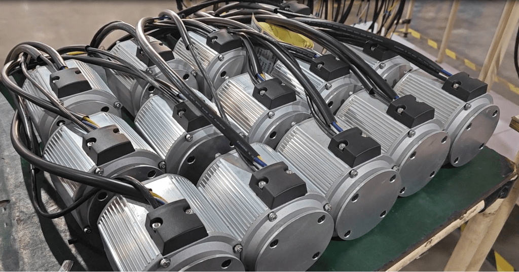
The Science of Silence: What Makes an Electric Motor Quiet?

In an increasingly automated and electrified world, noise is more than just a distraction—it’s a measurable indicator of wasted energy, poor design, and reduced operator comfort. For manufacturers and OEMs in sectors like material handling, medical mobility, and automated logistics, the demand for silent, high-performance drive solutions has never been higher.

At Rotontek, our engineering philosophy is built on delivering high torque and high efficiency with an absolute minimum of acoustic output. The question, “What makes a motor quiet?” drives our design process and is key to understanding the superior performance of our specialized drive series. A truly quiet motor is a masterpiece of precision engineering, addressing three primary sources of noise: mechanical, electromagnetic, and aerodynamic. This holistic approach is why we’ve earned a reputation as a trusted gear motor manufacturer.

Understanding the Sources of Motor Noise

Noise in any electric motor system originates from vibration, which then radiates sound waves. By isolating and minimizing these vibrations at the design stage, we can achieve the exceptional quietness that defines our product lines.

1. Mechanical Noise: The Challenge of Friction and Contact

Mechanical noise is arguably the most complex source to eliminate, especially in gear-driven systems. It arises from the physical interaction of moving parts:

Bearings: Poorly fitted or low-quality bearings can generate rattling, buzzing, or whining sounds. Our motors utilize preloaded bearings with minimal internal clearance, which virtually eliminates the ball-rattling noise and ensures each rolling element follows the same path, resulting in smoother operation.

Gears: The meshing of gear teeth is a significant source of noise in any low noise gear motor. When traditional spur gears engage, the force is transmitted abruptly. To counter this, Rotontek utilizes forged alloy steel gears with precision fine tooth grinding. This high-precision processing ensures the surfaces are smooth, and the pitch accuracy is maximized. In many of our assemblies, like the transaxle series, we employ special tooth patterns, such as helical teeth, which allow the teeth to mesh gradually. This gradual engagement results in a smoother, continuous transfer of force, significantly reducing impact noise and vibration.

Assembly and Alignment: Loose components, or misalignment between the motor and the gearbox, can cause structural vibrations. We utilize high-precision casings and standardized, rigid production processes to ensure a secure, perfectly concentric fit between all components, preventing the structure itself from acting like a loudspeaker.

2. Electromagnetic Noise: The Vibration of the Core

Magnetic forces are inherent to the operation of an electric motor, but when unbalanced, they generate noise. This electromagnetic noise, often heard as a high-pitched hum or buzz, is caused by the attraction and repulsion forces within the stator and rotor structure:

Cogging Torque and Torque Ripple: The interaction between the magnetic poles and the stator teeth causes variations in torque as the motor rotates, known as cogging torque and torque ripple. These variations create vibration. We mitigate this through advanced design techniques, including:

Optimal Slot/Pole Combinations: Selecting fractional slot/pole combinations that minimize the variation in magnetic reluctance.

Skewing: By skewing the stator slots or the magnets, the magnetic force is distributed more evenly across the rotational path, effectively smoothing out the ripple and reducing vibration.

Air Gap Uniformity: An uneven air gap between the rotor and stator creates unbalanced magnetic forces, which can deform the components and cause a buzzing noise. Precision manufacturing ensures the air gap is maintained with exceptional uniformity.

Rotontek’s Integrated Noise Reduction Series: The Power of Design

As a specialized gear motor manufacturer, we address the need for quiet power not with a single feature, but with a complete series of integrated drive solutions.

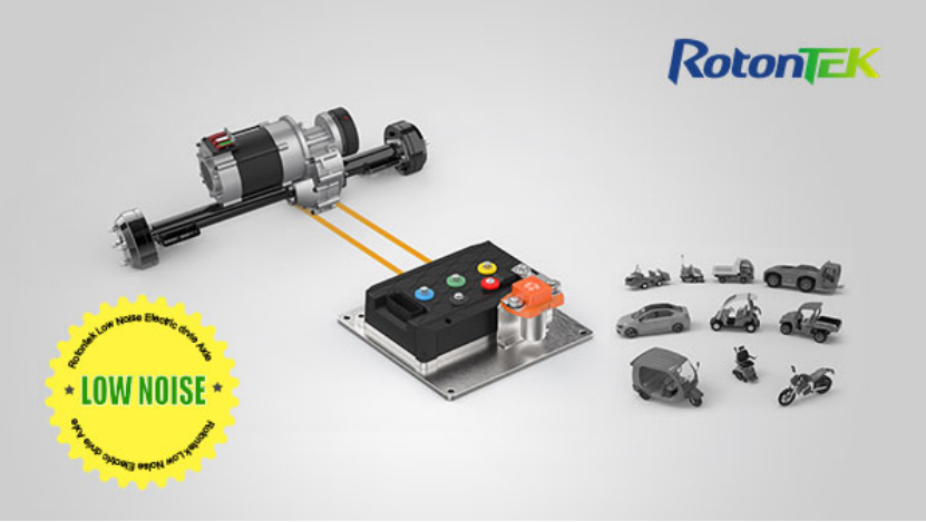
The LD62 Series, which includes models in the 3000W-5000W range, exemplifies what a modern, low noise gear motor can achieve.

Noise Specification: The LD62 series maintains a noise level restrained to ≤ 54 dB, a level comparable to a quiet office or household refrigerator—significantly below the noise threshold of traditional drive systems.

Precision and Power: This series uses high-precision, alloy steel hard tooth surface gears, ensuring durable and robust performance while maintaining the quiet operation required for applications like electric golf carts, intelligent logistics vehicles, and cleaning machines.

Integrated Safety: Furthermore, these units often incorporate an Electromagnetic Intelligent Brake System, which provides reliable, responsive stopping power without adding mechanical friction noise. The unit is designed with a high protection level, such as IP55, making it dustproof and waterproof for reliable long-term outdoor use.

3. Aerodynamic Noise: Quieter Cooling

Aerodynamic noise, is generated by the cooling fan and the turbulence of air flowing around the high-speed rotating components. While often less of a factor in fully enclosed systems, it must still be addressed:

Fan Optimization: In applications where a fan is required, the design of the fan blades is optimized to reduce air turbulence and minimize the siren effect that can occur at high speeds.

Enclosure Design: Our fully enclosed motor designs, particularly the integrated electric transaxles, inherently minimize aerodynamic noise by eliminating the need for complex, air-moving cooling structures that often contribute to turbulence.

The Advantage of Rotontek Precision

The relentless focus on reducing vibration and noise is fundamental to the value we provide our customers. A quieter motor is a more efficient motor, as noise is simply energy that has been converted into wasted acoustic waves. By investing in design optimization, superior materials, and high-precision manufacturing processes, we ensure that every Rotontek product delivers maximum power with minimum acoustic pollution.

Our integrated approach—addressing mechanical gear noise, electromagnetic force balance, and aerodynamic flow—allows us to consistently deliver a low noise gear motor that enhances the operator experience, meets strict regulatory standards, and provides a tangible competitive advantage for equipment built by our partners. This commitment to engineering intelligence is what drives our brand and continues to position Rotontek as a leader in the industrial electric motion field.

The Silent Powerhouse: Understanding How the PMSM Motor Works

The shift to electric mobility and automation has placed a spotlight on the Permanent Magnet Synchronous Motor (PMSM). This motor technology is rapidly becoming the standard for applications that demand high efficiency, precise control, and exceptional power density—from advanced logistics platforms (AGVs) to specialized low-speed electric vehicles.

At Rotontek, we are committed to providing the market with the most efficient and reliable electric drive systems. Our expertise lies in integrating these high-performance motors with advanced control units. This article provides a clear look at the internal mechanics of how the PMSM motor works and why its design makes it fundamentally superior for modern electric drive solutions.

The Fundamental Structure: Stator, Rotor, and Magnets

Unlike older motor designs that rely on brushes or induced current, the operation of a PMSM motor is defined by the interaction between its two core parts: the stator and the rotor.

The Stator

The stator is the stationary outer shell of the motor. It is composed of highly permeable steel laminations wound with copper coils. When a three-phase Alternating Current (AC) is applied to these windings by the motor controller, it creates a powerful magnetic field that rotates around the stator. The speed of this field is dictated precisely by the frequency of the applied AC current.

The Rotor

The rotor is the rotating inner part of the motor connected to the drive shaft. Its distinguishing feature is the presence of permanent magnets, typically made from rare-earth materials like Neodymium Iron Boron. These magnets generate a constant, powerful magnetic field without requiring any external power source.

Rotontek’s Focus: Interior Permanent Magnet (IPM) Design: While some PMSMs use surface-mounted magnets, our advanced IPM motors (as seen in our specialized drive systems) feature magnets embedded within the rotor. This Interior Permanent Magnet design offers superior mechanical robustness, better protection for the magnets at high rotational speeds, and allows the motor to harness an additional torque component called reluctance torque, further boosting performance and efficiency.

The Working Principle: Perfect Synchronization

The core operational principle that defines the Permanent Magnet Synchronous Motor lies in the word “synchronous.”

Magnetic Attraction: The powerful, fixed magnetic field of the rotor’s permanent magnets is constantly being attracted and chased by the magnetic field rotating in the stator.

Lockstep Motion: Because the rotor’s field is permanent and does not need to be generated by induction (unlike an induction motor, which requires slip), the rotor locks into “synchronism” with the stator’s rotating magnetic field.

Speed Control: The speed of the rotor is therefore perfectly and precisely controlled by the frequency of the AC current supplied to the stator. If the controller increases the frequency, the stator field rotates faster, and the rotor follows immediately and exactly in lockstep.

This synchronous operation is why PMSM motors are highly valued: they eliminate the efficiency-robbing “slip losses” characteristic of induction motors, ensuring that maximum electrical energy is converted into mechanical torque.

The Rotontek Advantage: Efficiency and Power Density

The unique design of the PMSM offers distinct benefits that translate directly into operational cost savings and superior vehicle performance for our partners.

1. Unmatched Efficiency

Since the rotor’s magnetic field is permanent, no electrical energy is wasted to create it. This elimination of rotor copper losses is a significant factor, allowing the efficiency of a high-quality PMSM motor to often exceed 95% under rated load conditions. This translates to extended battery range for electric vehicles and lower energy consumption for stationary industrial systems.

2. Superior Power Density

The use of powerful rare-earth magnets allows a PMSM to generate more torque in a smaller, lighter package compared to an induction motor of the same output power. In space-constrained applications—such as integrated electric transaxles for cleaning machines or medical mobility devices—this high power density is indispensable.

3. Advanced Control via Field-Oriented Control (FOC)

The precise, synchronous nature of the PMSM makes it an ideal match for sophisticated electronic controllers. The motor controller uses advanced algorithms, such as Field-Oriented Control (FOC) or Vector Control, to precisely regulate the current supplied to the stator. FOC effectively allows the motor to behave like an ideal DC motor, enabling the controller to independently manage the torque-producing current and the flux-producing current, resulting in:

Exceptional Dynamic Response: Instantaneous torque adjustment.

Silent Operation: Near-perfect sinusoidal current waveforms minimize acoustic noise.

High-Speed Control: Allows for the efficient use of field-weakening to push speeds far above the motor’s base speed.

Rotontek’s PMSM Motor Series: Driving Specialized Mobility

At Rotontek, the PMSM motor is the core technology across many of our specialized drive product lines, particularly our Integrated Permanent Magnet Synchronous Electric Motors and Transaxles. By offering the technology in a series of scalable units, we ensure our partners can match the motor’s capabilities perfectly to the application’s needs.

Conclusion

The integration of the high-efficiency PMSM motor within our sealed, compact drive units ensures our customers receive a single, drop-in solution that maximizes energy conversion and requires minimal maintenance, securing the path to high-performance electric drive systems.

Why Do Brushless Motors Need a Controller?

The global shift toward electrification in industrial and mobility applications—from AGVs and forklifts to electric wheelchairs—is driven by the superiority of Brushless DC (BLDC) motors. These motors offer higher efficiency, greater power density, and a significantly longer lifespan compared to traditional brushed motors. However, this superior performance comes with one crucial prerequisite: the absolute necessity of a specialized electric motor controller.

At Rotontek, we specialize in integrated electric drive systems for partners. We know that the motor is only as good as the intelligence that drives it. The controller is not an accessory; it is the electronic heart that replaces the mechanical components of older motors, turning a coil of wire into a powerful, precisely controlled machine. Understanding this relationship is key to designing high-performance electric vehicles and automated equipment.

The Fundamental Flaw: No Mechanical Commutation

To understand why a brushless controller is mandatory, one must first understand how a motor spins. All DC electric motors rely on a process called commutation—the continuous reversal of the electrical current flowing into the motor coils to maintain continuous torque in one direction.

The Brushed Motor (The Mechanical Solution)

In a traditional brushed DC motor, commutation is handled mechanically. It uses physical brushes (carbon blocks) that make contact with a spinning commutator (segmented metal cylinder). As the rotor turns, the brushes physically switch the current’s direction to the appropriate windings.

Pros: Simple, direct connection.

Cons:Friction, wear-and-tear (requires maintenance), heat generation, electromagnetic interference (EMI), and fixed timing that limits efficiency.

The Brushless Motor (The Electronic Requirement)

A BLDC motor, by definition, has no brushes or commutator. The permanent magnets are on the rotor (the moving part), and the coil windings are on the stator (the stationary part). While the lack of brushes eliminates friction, wear, and maintenance—which are massive advantages for longevity—it introduces a challenge: there is no physical mechanism to switch the current to the windings.

The rotating magnetic field required to pull the rotor forward must be created externally by sequentially powering the stator windings in the correct order and at the exact right time. This is the controller’s core function: Electronic Commutation. Without a controller, a BLDC motor cannot even start, let alone run efficiently. It is effectively a sophisticated engine without a fuel delivery or ignition system.

More Than Just Switching: The Controller’s Intelligence

The modern electric motor controller does far more than just switch the phases. It is a highly advanced computer that manages power delivery, safety, and efficiency using real-time data.

1. Precision Rotor Positioning

The controller must constantly know the exact angular position of the rotor’s permanent magnets relative to the stator windings. It achieves this through feedback, typically using:

Hall Effect Sensors: Physical sensors embedded in the motor that provide direct feedback on magnet position.

Sensorless Control: Advanced algorithms that infer the rotor’s position by measuring the Back Electromotive Force generated in the un-energized motor windings.

Using this position data, the controller’s microprocessor uses techniques like Field-Oriented Control (FOC) to modulate the power precisely.

2. Advanced Performance and Safety Management

Beyond basic rotation, the controller delivers the high-level features essential for safe and reliable commercial operation:

Speed and Torque Regulation: It modulates the voltage/current using Pulse Width Modulation (PWM) to adjust the speed and torque based on user input (e.g., a joystick or accelerator pedal).

Regenerative Braking: A critical feature in e-mobility, the controller manages the process of converting the motor into a generator during deceleration, returning kinetic energy to the battery and extending the vehicle’s range.

Comprehensive Protection: The controller is the system’s guardian, featuring built-in safeguards against over-current, under-voltage, over-voltage, and over-temperature conditions, ensuring the motor and battery are protected from damage and maximizing the system’s longevity.

Rotontek’s Series of Brushless Controller Solutions

At Rotontek, we offer a powerful series of integrated controllers engineered for the specific demands of our industrial partners. Our products are designed not just to power motors, but to manage entire drive systems with unmatched precision and safety.

The ID Series: Integrated Mobility Control

Our ID Series of controllers exemplifies the integration of power and intelligence, perfect for applications like electric wheelchairs, mobility scooters, and compact utility vehicles.

ID200 Series: This series is a high-performance brushless controller utilizing T1’s mainstream DSP chip technology paired with advanced sine wave vector control.

Promoted Product Specifications (ID200): It supports a versatile Rated Voltage of DC 24V/36V/48V. It provides a robust Continuous Current of 30A (for 60 minutes) and a Peak Current of 75A (for 10 seconds), ensuring it can handle demanding start-up and acceleration loads. Critically, it features CAN Communication, allowing seamless integration and diagnostics within a complex vehicle system. The inclusion of anti-skid and electromagnetic brakes further enhances its safety profile.

ID500 & ID510 Series: These controllers build on the ID200’s foundation, adding specialized features like AI Smart Speed Control and advanced motor load automatic compensation, which maintains stable speeds even when encountering obstacles or climbing hills—a vital factor in ensuring user comfort and safety in medical and personal mobility devices.

ID600 Series (3KW~5KW): Engineered for heavier applications like electric sweepers and tugs, the ID600 series handles higher power demands, featuring peak currents up to 200A and supporting a wider range of sensor types (Hall, Incremental Encoder, SIN/COS Encoder) for ultimate flexibility in system design.

Conclusion

By choosing a solution from the comprehensive Rotontek electric motor controller range, our partners are equipping their products with the highest levels of efficiency, safety, and operational control available, solidifying our role as a driving force in specialized electric mobility.

Selecting a Motor Controller Supplier in 2026: A Strategic Guide

electric motor controller

With transportation and industrial equipment rapidly advancing toward electrification and intelligence, the electric motor controller, as the brain of the drive system, directly determines a product’s range, safety, user experience, and long-term reliability.

Therefore, selecting a motor controller supplier is not merely about choosing a component partner, but also about securing the future market competitiveness of your core product.

To support your decision-making, this article will systematically analyze the four strategic dimensions for evaluating motor controller manufacturers and reveal two common yet critical pitfalls in the selection process.

Deep Integration and Modularity

A notable trend in the current electric motor controller market is the growing preference for highly integrated solutions that converge the motor, Battery Management System (BMS), and Vehicle Control Unit (VCU).

These integrated designs do more than reduce footprint and wiring complexity; they significantly boost energy efficiency and system responsiveness by optimizing inter-component coordination.

A suitable supplier should demonstrate exceptional technical flexibility. For instance, rather than offering a one-size-fits-all product, Rotontek provides tailored motor control solutions, including brushless motor controllers, proportional controllers, and hybrid units.

Whether for specialized equipment requiring high torque at low speeds or passenger vehicles prioritizing smooth, quiet operation, we can seamlessly embed our technology into the customer’s system through a modular design philosophy, achieving a perfect harmony of hardware and software.

Quality, Reliability, and Global Compliance

An electric motor controller must operate reliably over the long term in extreme real-world environments characterized by intense vibration, thermal stress, high humidity, and electromagnetic interference.

Consequently, a supplier’s ability to guarantee stability is a core consideration. This challenge demands a stringent quality management system that spans the entire lifecycle, from initial design and production to final validation.

Rotontek treats reliability as its lifeline, having established an end-to-end quality control framework:

  • Precision Material Selection:We insist on using automotive-grade or high-tier industrial-grade components to ensure baseline durability.
  • Advanced Manufacturing:We employ automated precision production lines and rigorous process standards to eliminate human error.
  • Comprehensive Testing & Validation:Every DC brushless controller and high-performance unit must undergo a grueling battery of tests. This includes electrical performance, environmental adaptability, electromagnetic compatibility (EMC), and accelerated durability testing simulating thousands of hours of real-world operational conditions.

Professional Depth for Full-Scenario Applications

Different application scenarios have vastly different performance requirements. For instance, golf carts demand smooth, quiet operation and reliable hill-holding capability, while forklifts require extremely high low-speed torque output and durability for frequent start-stop cycles. Generalized motor control solutions often struggle to meet all these specific needs.

Thus, whether a supplier possesses the ability to deeply understand niche scenarios and deliver customization is key.

Leveraging years of experience in specialized fields, Rotontek has accumulated a rich repository of application knowledge. We can perform deep customization and optimization for controllers targeting different sectors, covering tailoring torque response curves, overload protection thresholds, regenerative braking strategies, and communication protocols.

For applications requiring coordinated power, such as certain industrial machinery or specialized electric vehicles, we can also deliver sophisticated dual motor controller solutions, enabling precise torque vectoring and synchronized control.

In-Depth Service and Agile Response Ecosystem

In a market of rapid technological iteration, a supplier’s service and response capabilities are also integral to core competitiveness. This involves the expertise of the technical support team, the responsiveness to customization development requests, and the efficiency of remote diagnostics and on-site support.

Two Critical Pitfalls to Avoid in Procurement Decisions

Pitfall 1: Focusing Solely on Peak Power

Many purchasers overemphasize the peak power parameter, believing that higher is always better. However, for most equipment, continuous, stable, and efficient output in the mid-to-low power range is the core of daily operation.

An electric motor controller with high peak power but poor continuous output capability and low efficiency will not only fail to deliver expected performance but may also cause motor overheating, severely impacting range and reliability.

Pitfall 2: Blindly Pursuing Low Price

Low-cost controllers often achieve their price point by utilizing sub-standard components, over-simplifying protection circuits, and bypassing rigorous validation. While these units may function in the short term, they harbor significant long-term risks.

Unstable current output can lead to motor insulation breakdown, and poor EMC (Electromagnetic Compatibility) can interfere with sensitive onboard electronics. Most importantly, inferior charge/discharge management logic can cause irreversible degradation to expensive battery packs. Opting for a premium motor controller supplier like Rotontek may involve a higher upfront investment. Still, it yields a longer product lifecycle, lower failure rates, and superior protection for your most valuable core components.

Conclusion

In summary, selecting a motor controller supplier must extend beyond simple parameter comparisons. It necessitates a comprehensive evaluation across four strategic dimensions: system integration capability, quality and reliability assurance, scenario-specific expertise, and a full lifecycle service ecosystem. Equally critical is avoiding the two common pitfalls of peak power fixation and low-price bias.

When determining the future competitiveness of your product, choosing Rotontek as your partner represents a prudent and strategic investment—one that secures a decisive edge in long-term performance and market success.

The Core of Electric Mobility: Understanding the Motor Control in EV Systems

The rapid global shift toward electrification is not just a trend; it’s a fundamental change in how the world moves. At the heart of every Electric Vehicle (EV)—from the smallest mobility scooter to the heaviest industrial transport—lies the motor control system. It is the critical technology that translates the driver’s intent into precise, efficient motion. Without a sophisticated control system, the potential of the electric motor remains untapped.

At Rotontek, we specialize in the complete electric drivetrain solution, recognizing that the efficiency and performance of an EV are determined by the synergy between the motor, the gearbox, and, most importantly, the controller. Our focus is on providing robust, high-precision components for OEMs, manufacturers of low-speed electric vehicles, material handling equipment, and specialized industrial automation applications. This article provides a deep dive into the function, components, and significance of this crucial EV technology, highlighting how our integrated systems drive better performance.

The Brain of the Drivetrain: What is Motor Control in EV?

The EV motor control unit (MCU), often simply called the motor controller, is the electronic brain that manages the flow of electrical energy between the high-voltage battery pack and the electric motor. Its core function is to regulate the speed, torque, and direction of the motor based on inputs from the vehicle’s accelerator, brake pedal, and other sensors.

In simple terms, an EV motor is typically an AC motor, such as a Permanent Magnet Synchronous Motor (PMSM) or an Induction Motor, or a BLDC motor (Brushless DC). However, the vehicle’s battery stores power as Direct Current (DC). The motor controller’s primary task is to act as an inverter, converting the battery’s DC power into the variable frequency, variable voltage Alternating Current (AC) required to spin the motor. This real-time, high-speed conversion is what allows for smooth acceleration, deceleration, and energy management.

The Essential Functions of an EV Motor Controller

A modern motor control unit does far more than just turn the motor on and off. It performs several critical functions vital to an EV’s operation and overall efficiency:

Power Conversion and Control: It uses power electronic components, like MOSFETs or IGBTs, to rapidly switch the DC current, creating the necessary AC waveforms for the motor. Advanced control algorithms, such as Field-Oriented Control (FOC), enable separate and precise regulation of the motor’s torque and flux, maximizing efficiency across all operating speeds.

Torque and Speed Regulation: The controller continuously monitors motor and vehicle parameters, adjusting the current to meet the driver’s command. Whether the vehicle is starting up, climbing a hill, or maintaining a steady cruise, the controller ensures a smooth and immediate response.

Regenerative Braking: This is a key feature of electric mobility. When the driver slows down, the controller reverses the process. It allows the motor to act as a generator, converting the vehicle’s kinetic energy—which would otherwise be wasted as heat in friction brakes—back into electrical energy and sending it to recharge the battery. This feature significantly enhances a vehicle’s range and longevity.

Protection and Diagnostics: The MCU constantly monitors temperature, current draw, and voltage to protect the expensive motor and battery components from overload, short circuits, and overheating, ensuring the system’s longevity and safety.

Enhancing Performance with Rotontek’s Integrated Solutions

Achieving optimal EV performance is not about buying separate, standalone components—it’s about seamless integration. Our philosophy at Rotontek is to deliver complete, optimized systems. Our expertise goes beyond the motor itself, focusing on the sophisticated integration that defines a truly efficient vehicle.

We offer a range of comprehensive drive systems, including our high-performance transaxles and integrated drive axles, which bundle the motor, gearbox, and often the controller, into a single, compact unit. This integrated design is essential for manufacturers of vehicles where space and weight are critical constraints.

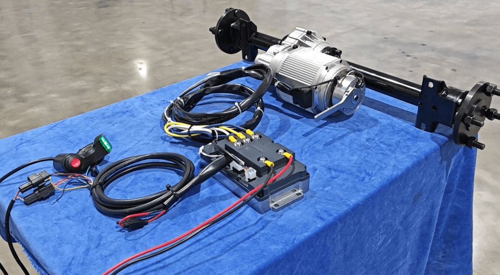
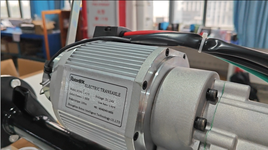
Take, for example, our permanent magnet brushless transaxle series, which are designed to support a wide range of low-speed electric mobility applications, from small electric tugs to golf carts. The 800W Permanent Magnet BLDC Transaxle ND42 800 is a prime example of our commitment to integrated quality. This specific transaxle is a single, robust unit, combining a high-efficiency brushless DC motor and a differential. It offers an impressive Rated Power of 800W and delivers a Rated Torque of 102.7Nm /57.9Nm, perfect for applications requiring reliable low-speed, high-torque operation. With a customizable operating voltage ranging from 24V to 48V and a low-noise design, it is engineered for long-lasting, low-maintenance performance.

The Future of Electric Drive is Precision Control

As the electric vehicle market matures, the demand for a more precise and efficient motor drive for electric vehicle applications will only increase. Our partners require not just power, but control—the ability to fine-tune energy consumption, maximize regenerative energy capture, and ensure a low noise signature for better operational environments.

The continuous evolution of power electronics allows us to push the boundaries of energy efficiency. The advanced control algorithms within a Rotontek system ensure that our motors operate at their peak efficiency, minimizing heat waste and extending battery life. By providing a scalable series of motor and transaxle combinations—from 150W low-power units to heavy-duty 20KW solutions—we ensure that our partners can select the optimal, ready-to-integrate system for any electric mobility platform.

Conclusion

The motor controller is truly the intelligence of the electric powertrain, and its quality dictates the vehicle’s success. By choosing Rotontek as your partner, you are securing a commitment to engineering excellence, optimized for the next generation of silent, powerful, and efficient electric vehicles.

How Does Your Motor Controller Impact Overall System Performance?

Understanding the impact of your motor controller is crucial for optimizing your entire system. As a supplier, we know that the right controller is not just a component; it is a critical determinant of efficiency, responsiveness, and longevity. This knowledge helps you make informed decisions that directly affect operational costs and machine reliability. Selecting an appropriate controller ensures your application performs as intended from the start.

Motor Controller Efficiency Effects

The efficiency of a motor controller directly influences the overall energy consumption and thermal performance of a system. An inefficient controller generates excess heat, requiring more robust cooling solutions and reducing the operational lifespan of both the controller and the motor. This energy loss is critical in battery-powered applications, where it directly shortens runtime. High efficiency, conversely, maximizes battery life and minimizes heat generation. The design of a high power brushless motor controller often focuses on minimizing switching and conduction losses in its power semiconductors. This is achieved through careful component selection and optimized gate driving techniques. The overall system efficiency is a product of the motor and controller working in harmony, making the controller’s role fundamental to achieving peak performance and energy savings in any electromechanical system.

System Response Time Changes

System response time, defined by how quickly a motor reacts to a command signal, is heavily dependent on the controller’s processing speed and control algorithm performance. A slow controller introduces lag, resulting in poor positional accuracy, unstable velocity control, and reduced productivity in automated systems. This is particularly critical in applications requiring precise motion profiles, such as robotics or conveyor systems. The processing capability of a brushless drive motor controller determines how fast it can execute complex control loops for current, speed, and position. Faster processing allows for higher loop frequencies, leading to tighter control and better disturbance rejection. Ultimately, the controller’s speed dictates the agility and precision of the entire motor system, impacting everything from cycle times to the quality of the finished operation.

Torque Ripple Control Importance

Torque ripple refers to periodic variations in output torque, which can cause undesirable effects such as vibration, audible noise, and speed fluctuations. These variations stem from non-ideal characteristics in the motor and imperfections in the control signals from the drive. In precision applications, excessive torque ripple can degrade the quality of machining, printing, or other sensitive processes. A motor controller mitigates torque ripple through advanced techniques like field-oriented control and precise sinusoidal commutation, which smooth the current delivered to the motor windings. By minimizing these torque pulsations, the controller ensures smoother motor operation, reduced mechanical wear on connected components, and a higher quality of motion control. This leads to improved performance and greater consistency in the final application output.

Conclusion

Ultimately, the motor controller is a force multiplier for your entire electric drive system. Its impact on efficiency dictates your operational range and costs, its precision defines your machine’s capability and safety, and its resilience ensures long-term reliability. Choosing a controller that excels in these areas is an investment in the performance and longevity of your vehicle. For systems that demand robust integration of power, control, and durability, exploring the solutions from Rotontek can provide a cohesive approach to electrifying mobile platforms.

What is a Brushless DC Motor?

Understanding brushless DC (BLDC) motor technology is fundamental for us as a supplier to provide effective solutions. This knowledge allows us to match the right motor characteristics to your specific application needs, whether for industrial machinery or electric mobility. We can guide you on the benefits of efficiency, longevity, and control that this motor type offers. This ensures you receive a component that integrates seamlessly and performs reliably in your system.

My Internal Motor Design

A brushless DC motor fundamentally reimagines the traditional brushed motor by inverting its architecture. In a BLDC motor, the permanent magnets are located on the rotor, which is the part that spins. The wire windings, which generate magnetic fields, are situated on the stationary stator surrounding the rotor. This design eliminates the need for physical brushes and a commutator to transfer current to the spinning part. Instead, the motor relies on external electronic control to sequentially energize the stator windings, which pulls the magnetized rotor along. This inversion is key to the motor’s advantages, including reduced friction, lower maintenance, and the ability to dissipate heat more effectively from the stator. The absence of brush sparking also allows for operation in volatile environments. This robust internal design is a hallmark of a modern dc brushless motor, providing a reliable foundation for various demanding applications.

My Electronic Commutation System

The electronic commutation system is the intelligent brain that replaces the mechanical brush and commutator assembly. It consists of a controller and sensor or sensorless feedback system that precisely determines the rotor’s position. This information is used to electronically switch the current flowing through the stator windings in the correct sequence. By continuously energizing the windings just ahead of the rotor’s permanent magnets, the system creates a magnetic drag that results in smooth and continuous rotation. This precise control allows for exceptional speed regulation, high torque at low speeds, and efficient operation across a wide performance range. The sophistication of this system enables advanced features like programmable acceleration and deceleration profiles. This electronic control is a core component of an interior permanent magnet synchronous motor, ensuring optimal performance and responsiveness for complex drive tasks.

My Rotating Magnetic Fields

The principle of operation for a brushless DC motor hinges on the creation of a rotating magnetic field within the stator. The electronic controller delivers power to the stator windings in a specific, cyclical pattern. This sequential energization of the windings generates a magnetic field that effectively rotates around the stationary stator. The permanent magnets on the rotor are then attracted to this moving magnetic field, causing the rotor to turn in sync with it. The speed of the motor is directly controlled by the frequency at which the windings are switched, determining how fast the magnetic field rotates. The torque produced is related to the strength of the magnetic interaction between the rotor’s magnets and the stator’s field. This method of using a electronically generated rotating field to pull the rotor is what allows for such precise and efficient motion control without any physical contact.

Conclusion

Ultimately, a brushless DC motor represents a smarter, more durable approach to electrification, delivering the performance and reliability that modern applications demand. Its principles of electronic commutation and efficient magnetic design translate directly into lower lifetime costs and greater control. We are committed to refining this technology to solve real-world challenges in diverse sectors. To explore how our specific implementations can benefit your project or product, we invite you to learn more about our portfolio at Rotontek.

Are PMSM Motors Easy to Maintain?

For any supplier, understanding the maintenance profile of your components is critical for customer support and product reliability. The question of whether PMSM motors are easy to maintain directly impacts your operational costs and service planning. This analysis outlines the key maintenance aspects to help you manage your fleet or product line effectively. A clear grasp of these requirements ensures long-term performance and customer satisfaction.

Rotor Magnet Temperature Monitoring

Monitoring the rotor magnet temperature is a fundamental maintenance task for a permanent magnet synchronous motor. The high-strength rare-earth magnets are sensitive to temperature; excessive heat can cause partial or irreversible demagnetization, leading to a permanent loss of torque and efficiency. We recommend using embedded temperature sensors and thermal models to monitor rotor conditions in real-time, especially during high-load or high-speed operations. Preventive maintenance schedules should include verifying the accuracy of these monitoring systems. Ensuring adequate cooling, such as through liquid cooling jackets or forced air, is equally critical to maintain the magnets within their safe operating temperature range, which directly preserves motor performance and longevity.

Stator Winding Insulation Checks

Regular inspection of the stator winding insulation is essential for the operational integrity of any pmsm motor. The insulation system is subjected to significant thermal cycling and electrical stresses from the high-frequency PWM waveforms produced by inverters. Over time, this can lead to insulation degradation, partial discharges, and eventually, short circuits. We advise periodic checks of insulation resistance, typically using a megohmmeter, to detect moisture ingress or contamination. Visual inspections for signs of physical damage, overheating, or carbon tracking are also vital. Keeping the windings clean and dry prevents premature failure, making this a straightforward but non-negotiable part of a predictive maintenance strategy.

Bearing Lubrication Interval Adherence

Adherence to prescribed bearing lubrication intervals is a primary mechanical maintenance requirement. Bearings support the rotor and are subject to continuous mechanical stress. Using the incorrect lubricant type or quantity, or extending service intervals beyond recommendations, can lead to increased friction, overheating, and eventual bearing seizure. We follow manufacturer guidelines for relubrication schedules and lubricant specifications based on operational speed and temperature. For sealed bearings, the focus shifts to monitoring for signs of wear or contamination, as they are typically lubricated for life. Proper lubrication minimizes vibration and noise, directly contributing to the motor’s smooth operation and preventing unplanned downtime.

Conclusion

In summary, PMSM motors are indeed easier to maintain compared to many traditional alternatives, thanks to their brushless, durable design. The maintenance regimen focuses on supporting systems rather than the motor’s core magnetic components, offering users predictable performance and reduced servicing costs. For organizations seeking reliable powertrain solutions, this inherent advantage is a significant operational benefit. To explore how these principles are applied in specific products, we invite you to review the technical specifications and support resources available directly from Rotontek.

What is a Permanent Magnet Synchronous Motor?

Understanding the fundamentals of a permanent magnet synchronous motor is important for selecting the right component for your application. As a supplier, we know that this knowledge helps you evaluate performance, efficiency, and integration requirements. This article provides a clear, factual overview of how these motors work. This information supports your decision-making process when sourcing components.

Magnet Rotor Construction

The defining feature of a permanent magnet synchronous motor is its rotor, which is embedded with powerful permanent magnets instead of windings. These magnets, often made from rare-earth materials like neodymium, create a constant magnetic field. The rotor’s construction can be either surface-mounted (SPM) or interior (IPM), with the latter embedding magnets inside the rotor laminations for structural integrity and higher speed capability. This design eliminates the need for rotor current and the associated losses, such as those from induction, which is a primary reason for its high efficiency. The robust magnetic field interacts directly with the rotating magnetic field generated by the stator, enabling precise torque production and reliable operation across various speeds and loads.

Stator Winding Design

The stator in a permanent magnet synchronous motor is similar to that of an induction motor, consisting of a laminated steel core with distributed windings. When alternating current is supplied to these windings, they produce a rotating magnetic field. The design and patterning of these windings are critical for creating a smooth, sinusoidal magnetic field that efficiently interacts with the permanent magnets on the rotor. In an interior permanent magnet synchronous motor, the stator field also utilizes magnetic reluctance torque, adding to the motor’s total output. Advanced control systems precisely manage the current in these windings to synchronize the stator’s rotating field with the rotor’s position, ensuring optimal performance, high power density, and minimal energy loss during conversion.

Synchronous Motor Operation

Operation is termed “synchronous” because the rotor’s rotation precisely locks in with the frequency of the alternating current in the stator windings. The rotor, with its permanent magnetic field, continuously aligns itself with the rotating magnetic field produced by the stator. This lock-step rotation eliminates slip, a phenomenon present in induction motors where the rotor lags behind the stator field. A rotor position sensor is typically used to provide real-time data to the controller, which adjusts the stator current accordingly to maintain this synchronization. This precise control allows for excellent speed regulation, high torque at low speeds, and stable operation across a wide range of conditions, making it suitable for applications demanding accuracy and efficiency.

Conclusion

The permanent magnet synchronous motor represents a significant leap in electromechanical design, offering a compelling combination of efficiency, power density, and control. Whether for precision industrial automation or the demanding world of electric transportation, this technology provides a foundational advantage. At Rotontek, we are committed to refining and applying this technology through our IPM motor series and integrated powertrain systems. We invite you to explore how our approach to efficient, reliable motor design can power your next project or product by visiting Rotontek to learn more about our specific solutions and capabilities.

What is a Brushless Controller?

Understanding brushless controllers is essential for selecting the right component for your electric vehicle project. As a supplier, we know that a reliable controller is the key to performance and longevity. This article explains the core functions of a brushless controller to help you make an informed decision. Knowing its role ensures you choose a component that matches your specific motor and application requirements.

Motor Speed Control Device

A brushless controller fundamentally serves as a motor speed control device. It acts as the brain of an electric motor system, interpreting input signals from a throttle or control system to dictate the motor’s rotational speed and torque output. By rapidly switching the power supplied to the motor’s windings on and off, a technique known as Pulse Width Modulation (PWM), it precisely controls the average voltage and current. This allows for smooth acceleration and deceleration, providing the user with fine-grained command over the motor’s performance. The reliability and precision of a brushless controller are therefore critical for the safe and efficient operation of various motor-driven applications, ensuring they respond accurately to user commands.

Electronic Commutation System

Unlike brushed motors that use physical contacts for commutation, a brushless motor requires an external system to sequence power. This is the primary role of the controller, which functions as an electronic commutation system. It uses sensor-based or sensorless methods to continuously monitor the rotor’s position. Based on this real-time data, the motor controller electronically switches the current flow through the motor’s three phases in a specific sequence. This creates a rotating magnetic field that pulls the permanent magnet rotor, resulting in continuous and smooth rotation. This process eliminates the friction, sparks, and wear associated with physical brushes, leading to a more efficient, quieter, and longer-lasting motor system with less required maintenance.

Power Management for Motors

A brushless controller is a sophisticated power management unit for motors. It acts as an intermediary between the power source, typically a battery pack, and the motor itself. One of its key functions is to convert the direct current (DC) from the battery into a three-phase alternating current (AC) that the brushless motor requires. The controller also regulates the voltage and current delivered to the motor, protecting it from potential damage caused by over-voltage, over-current, or overheating. Many controllers include low-voltage cutoff circuitry to prevent excessive battery discharge, which can prolong battery life. This comprehensive power management ensures the motor operates within its safe and efficient parameters, optimizing both performance and system durability.

Conclusion

In summary, a brushless controller is the essential intelligence behind efficient, modern electric motion, converting battery power into controlled mechanical work. Its technology enables the quiet, reliable, and low-maintenance operation we expect from today’s EVs and industrial drives. Selecting a controller matched to your specific voltage, current, and application requirements is key to optimal performance. We invite you to explore how our dedicated designs at Rotontek can provide the precise control and durability your project or product requires.