Power, Precision, and Stability: The Role and Series of Electric Jacks

In the world of heavy hauling, construction, logistics, and specialized vehicle support, stability and effortless lifting are non-negotiable requirements. Historically, this meant painstaking manual cranking or complex hydraulic setups. Today, however, the industry is transitioning to automated, precise solutions, and leading that charge is the electric jack.

An electric jack is a motorized lifting and stabilizing device that replaces manual effort with electrical power. By integrating an electric motor with a high-strength mechanical transmission, it provides controlled, effortless movement for lifting, leveling, and supporting heavy loads. At Rotontek, we view this technology as a core component of efficiency and safety across various heavy-duty industries, offering a series of jacks designed for specific torque and stability challenges, from semi-trailers to specialized platforms.

The Mechanism: How Electric Jacks Convert Power to Lift

The core function of an electric jack is to take the rotational power of a motor and convert it into linear thrust—a process that must be highly reliable, self-locking, and efficient.

1. The Motor and Transmission System

Unlike manual jacks that rely on muscle power turning a handle, electric leveling jacks utilize a DC electric motor connected to a gearbox. This gearbox reduces the high-speed, low-torque output of the motor into a low-speed, high-torque force suitable for lifting thousands of kilograms.

Worm Gear/Screw: The reduced torque is applied to a high-strength screw shaft. As the screw rotates, a nut or collar travels up or down the shaft, extending or retracting the jack’s inner leg.

Self-Locking Feature: A crucial safety feature is the inherent self-locking capability of the worm gear or screw drive. This mechanism ensures that when the motor power is removed, the load cannot force the jack back down, keeping the raised object securely in position without the need for a continuous power supply. This stability is vital when stabilizing heavy vehicles or construction platforms.

2. Control and Safety

Modern electric jack systems move far beyond simple on/off switches. They feature advanced controls, including:

One-Touch Operation: Simplified controls, allow for single-button deployment and retraction, dramatically improving speed and ease of use.

Intelligent Sensing: In electric leveling jacks, built-in sensors or Hall Effect technology monitor the extension of multiple jacks simultaneously, allowing a centralized control unit to automatically adjust the height of each leg until the vehicle or platform is perfectly level.

Safety Brakes: Patented power-off brakes are often incorporated to ensure immediate lock-down in the event of power loss, adding an extra layer of safety during operation.

Versatility in Application: The Rotontek Leveling Jack Series

The versatility of the electric jack system is best demonstrated by the wide range of heavy-duty applications it serves. Rotontek offers distinct series tailored to specific industrial and transport needs, focusing on high tonnage capacity and robust durability.

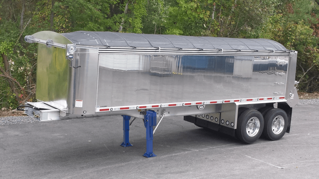
1. Semi-Trailer Landing Gear: Heavy-Duty Stabilization

One of the most demanding applications is supporting semi-trailers during loading and unloading when they are detached from the tractor. This requires supporting a significant portion of the trailer’s maximum gross weight, often on uneven terrain.

The Rotontek Semi-trailer 10T Leveling Jack (ND1OT-NG350) exemplifies our commitment to high-capacity stabilization.

ND1OT-NG350 Key Specifications:

Carrying Capacity (Single Jack): 10 Tons

Lifting Mechanism: Ball screw for high efficiency

Operation: One-button operation (approx. 80 seconds to position)

Protection Grade: IP56 (Corrosion-resistant and weather-proof)

Stability Feature: Patented screw reverse mechanism for superior shock absorption.

This type of electric leveling jack prevents “trailer tipping” during forklift operations and eliminates the back-breaking manual cranking, which is a significant ergonomic and safety advantage in high-volume logistics centers. We also offer a 20T Electric Landing Gear series, which features a pioneering transmission design incorporating a ball screw mechanism for superior energy-efficiency compared to conventional trapezoidal screws.

2. Specialized Industrial and Agricultural Platforms

Beyond transportation, the demand for stable, adjustable support extends to complex machinery that must operate with precision on un-level ground.

Agricultural Machinery: Large-scale planting and harvesting equipment often needs quick, accurate leveling before deploying specialized booms or components to ensure uniform results across sloped fields.

Construction Equipment: Modular construction sites, temporary structures, and specialized heavy lifting equipment require rapid, fail-safe stabilization. The portability and power of an electric jack series provide the necessary rigidity and ease of deployment.

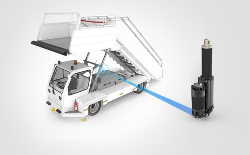
Aircraft Docking Systems: High-precision leveling and stabilization are essential for safety during aircraft maintenance and docking procedures.

3. Recreational Vehicle (RV) and Camper Leveling

While often seen in consumer applications, the underlying technology comes from the same robust industrial design principles. The need for precise, fast leveling in the RV industry—to ensure appliances function correctly and for user comfort—has driven the widespread adoption of multi-point electric leveling jacks. These systems use sensors to automatically determine the low corners and extend the jacks in sequence, achieving level in minutes, rather than the tedious manual process of using blocks and cranks.

The Rotontek Advantage: Durability and Customization

At Rotontek, our philosophy in the electric jack and leveling field centers on durability and tailored performance. Our jacks are manufactured from high-strength, high-quality steel with corrosion-resistant surface treatments, such as the electrophoretic process on our 10T jack, ensuring stable, long-term operation even in harsh outdoor and heavy-duty environments.

By offering a versatile series of jacks—from the high-efficiency ball screw designs in our trailer landing gear to the precision control found in our smaller lifting solutions—we ensure that every partner can find the specific torque, lift capacity, and control system required for their unique stabilization challenges.
The Lifeblood of Motion: What is the Fluid in a Hydraulic Power Unit?

At Rotontek, we believe that true engineering excellence is found in the powerful combination of electrical precision and hydraulic strength. From our compact power systems to our advanced linear actuators, the heart of our technology lies in the efficient transfer of force. This immense power is enabled by one crucial, often-overlooked element: the hydraulic fluid.

Understanding the Essential Functions of Hydraulic Fluid

The primary purpose of a hydraulic system is to take a small force and multiply it to achieve a powerful output, often lifting, pushing, or clamping heavy loads. This is achieved by exploiting the property of hydraulic fluid: its near incompressibility.

1. Power Transmission: The Core Function

In a hydraulic power unit, an electric motor drives a pump, which draws fluid from a reservoir and forces it through the circuit. Because the fluid is virtually incompressible, the pressure generated by the pump is transmitted uniformly throughout the system. This pressurized fluid acts on the pistons within actuators, converting the fluid energy back into powerful mechanical motion. This mechanism is central to the operation of a high-thrust device like the Rotontek 0.6–1.5T Electric Hydraulic Linear Actuator, which we will discuss in detail later.

2. Lubrication: Protecting Components

Moving parts within the hydraulic system, such as the pump’s gears and the actuator’s piston seals, require constant protection from friction and wear. The hydraulic fluid acts as a lubricant, coating these metal surfaces to reduce abrasive contact. Using a fluid with the correct viscosity and lubricating properties is vital to ensuring the long-term reliability and service life of the entire system. Without proper lubrication, heat generation would rapidly increase, leading to premature component failure.

3. Sealing: Preventing Internal Leakage

Beyond simply moving the components, hydraulic fluid also plays a crucial role in sealing. It fills the minute gaps between moving surfaces, such as the clearances between a pump’s gear teeth or the gap between a cylinder piston and its bore. This film of fluid prevents internal leakage, which could otherwise lead to a drop in system efficiency, ensuring that the pressure generated by the pump is directed entirely toward the work being performed.

4. Cooling: Thermal Management

Every time hydraulic fluid flows through the pump, control valves, and actuators, energy is converted, and friction is generated. This creates heat, which, if left unchecked, can degrade seals, thin the fluid, and damage components. The hydraulic fluid acts as a coolant, absorbing heat from the mechanical components and carrying it back to the reservoir or a heat exchanger, where it can be dissipated. This thermal management capability is essential for sustaining the duty cycle and lifespan of our compact power units.

The Different Faces of Hydraulic Fluid

Choosing the correct fluid is not merely a matter of finding the right viscosity; it’s about matching the fluid’s properties to the system’s operational demands.

Mineral Oil-Based Fluids: Derived from crude oil, these are the most common and cost-effective hydraulic fluids. They are typically enhanced with additives like anti-wear agents, corrosion inhibitors, and anti-foaming compounds to improve performance. They are suitable for most general industrial applications.

Synthetic Fluids: Chemically engineered for superior performance in extreme conditions. These are more expensive but offer exceptional thermal stability, oxidation resistance, and fire resistance, making them ideal for high-temperature or critical industrial settings.

Water-Based Fluids: Used primarily where fire resistance is a critical safety requirement, such as in mining or near high heat sources. These include water-in-oil emulsions and water-glycol solutions.

At Rotontek, we understand the diversity of our clients’ needs, from underwater robotics to high-force industrial lifters. The fluid choice directly impacts the performance of our machines, which is why our product manuals always provide clear guidance on fluid compatibility to maintain the warranty and ensure peak performance.

Rotontek’s Integrated Solution: The Electro Hydraulic Actuator Series

The advancement of hydraulic technology is moving towards smaller, more efficient, and fully integrated systems. This is where Rotontek’s proprietary line of actuators shines, particularly our compact electro hydraulic actuator series. This product line, which includes the formidable 0.6–1.5T Electric Hydraulic Linear Actuator.

The 0.6–1.5T Electric Hydraulic Linear Actuator: A Closer Look

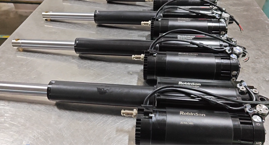
Unlike traditional hydraulic systems that require external pumps, hoses, and reservoirs, the Rotontek EHA integrates the motor, pump, cylinder, and fluid reservoir into a single, compact, sealed unit.

Key Specifications for the 0.6–1.5T Series (Example Model EHY4020100):

Maxium Thrust: 0.6-1.5 Tons

Power Rating: 300-800 W

Rated Voltage: DC 24-72 V

Plunger Pump Capacity: 0.3-0.6 cc/r

Waterproof Level: IP68

This all-in-one design dramatically reduces the risk of external leaks and contamination, directly improving the working life of the hydraulic fluid inside. The fluid itself is critical here: it facilitates the powerful mechanical motion while simultaneously lubricating the integrated plunger pump and the internal piston. The high-grade materials, including 304 stainless steel and aluminum alloy, along with the IP68 waterproof rating, ensure that the integrity of the hydraulic fluid is maintained even in the most demanding environments, such as underwater or in harsh industrial settings.

The Importance of Fluid Maintenance for Your Power Unit

No matter how sophisticated the design, the performance of an industrial hydraulic power unit is directly dependent on the quality and condition of its fluid. Since the fluid is responsible for lubrication and cooling, its contamination or degradation can quickly lead to catastrophic failure.

Contamination Control: Airborne dust, water, and metallic debris are the primary enemies of hydraulic fluid. Rotontek’s integrated, zero-leakage designs, like those found in our EHA and compact power unit series, are engineered to minimize this risk. However, using the specified fluid and following the recommended filtration schedule is essential for all systems.

Viscosity Management: The fluid’s viscosity (its resistance to flow) must remain within the operating range. If the fluid gets too hot, it thins out, reducing lubrication and sealing ability. If it gets too cold, it thickens, making it difficult for the pump to move it efficiently. Our robust control systems help maintain optimal operating temperatures, but choosing the correct viscosity grade for the environment is the first step.

The fluid in a hydraulic power unit is the heart of its operation—a multi-functional medium that transmits force, lubricates, seals, and cools. For optimal performance, a system requires careful selection and diligent maintenance of this fluid.

Conclusion

At Rotontek, we not only engineer advanced hardware, such as our integrated electro hydraulic actuator and reliable industrial hydraulic power unit series, but we also provide the technical expertise to ensure our clients understand and manage every component, guaranteeing powerful, precise, and long-lasting motion solutions for their most challenging applications.

Rotontek Electro-Hydraulic Actuators: High-Performance Solutions for Aerospace and Extreme Environments

As advanced equipment continues to evolve, the demands placed on actuator systems are becoming increasingly stringent. In industries such as aerospace, subsea engineering, and heavy industrial automation, actuators are expected to deliver not only high force output, but also exceptional reliability, compact integration, and stable performance in extreme environments. Traditional hydraulic systems often suffer from complexity and maintenance challenges, while purely electric actuators may struggle to meet high-load and environmental requirements.

Electro-hydraulic actuators (EHAs) have emerged as a balanced and reliable solution, combining the precision of electric control with the power density of hydraulic systems. At Rotontek, we develop electro-hydraulic actuator solutions designed specifically to meet these modern engineering challenges.

Rotontek Electro-Hydraulic Actuators: An Integrated Approach

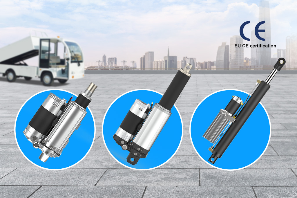
At Rotontek, our electro-hydraulic actuators are engineered with a focus on integration, durability, and performance. Our EHA solutions feature a revolutionary four-in-one design that integrates the electric motor, hydraulic pump, control unit, and actuator into a single compact system. This highly integrated architecture eliminates the need for external hydraulic power units, hoses, and complex system layouts.

Designed with IP68-rated ingress protection, our waterproof linear actuators are capable of operating reliably in harsh environments involving water, dust, oil, and corrosive substances. Compared with conventional hydraulic actuator systems, Rotontek EHAs offer significantly more compact pin-to-pin dimensions while maintaining high-load and high-force output. These characteristics make our actuators particularly suitable for mission-critical applications where space, reliability, and environmental resistance are essential.

Aerospace and High-End Aircraft Applications

One of the most demanding application areas for electro-hydraulic actuators is the aerospace sector. Aircraft systems require precise control, rapid response, and uncompromising safety under extreme operating conditions. At Rotontek, our EHA solutions are well suited for a wide range of aerospace and high-end aircraft applications, including aircraft wing doors, landing gear doors, thrust reversers, and auxiliary flight control actuators.

Aerospace applications benefit significantly from the high power density of electro-hydraulic actuators. Our systems are capable of delivering high force output within a compact envelope, allowing engineers to optimize space utilization without sacrificing performance. Fast response times and precise motion control ensure accurate positioning and smooth operation, which are critical for flight safety and system reliability.

Additionally, the IP68 protection of our actuators enables stable operation in environments exposed to rain, ice, hydraulic fluids, and temperature fluctuations. The combination of electric control and hydraulic power also provides inherent redundancy and safety advantages, supporting the stringent reliability requirements of aerospace systems. Through compact integration and stable high-frequency operation, Rotontek EHAs deliver dependable performance in critical aircraft functions.

Applications in Subsea and Harsh Industrial Environments

Beyond aerospace, Rotontek electro-hydraulic actuators are widely applicable in subsea and extreme industrial environments. Our waterproof linear actuators are designed for long-term underwater operation, making them ideal for subsea equipment, underwater valve control, marine platforms, and offshore engineering systems. Exceptional corrosion resistance and sealing performance ensure consistent operation even in saltwater and high-pressure conditions.

In harsh industrial environments, our EHAs are commonly used in heavy automation equipment, industrial machinery, and systems exposed to high humidity, dust, and corrosive agents. The robust design and high-force linear actuator capability allow our products to perform reliably where conventional electric actuators may fall short. Reduced maintenance requirements and long service life further enhance system availability and operational efficiency.

Key Technical Advantages of Rotontek EHA Solutions

Rotontek electro-hydraulic actuators combine several critical technical advantages into a single solution. By integrating electric control signals with hydraulic power transmission, our actuators provide precise control over motion, force, and positioning. This enables accurate and repeatable operation even under variable load conditions.

High power density is another defining advantage of our EHA technology. Our actuators deliver substantial force output from a compact structure, making them suitable for space-constrained applications. Fast response times allow systems to react quickly and accurately, improving overall operational performance and safety.

Energy efficiency is achieved through optimized electric-hydraulic coordination, reducing unnecessary energy loss and lowering operating costs over the system lifecycle. Our actuators are also designed for flexible integration, allowing them to be used in both new system designs and upgrades of existing hydraulic or electromechanical systems. Built-in safety features, including overload protection and emergency shutdown capabilities, further enhance reliability in mission-critical environments.

Engineering Support and Customized Solutions

At Rotontek, we do more than supply standard actuator products. Our engineering team works closely with customers to develop application-specific electro-hydraulic solutions based on operating environment, load requirements, stroke length, and installation constraints. From initial application evaluation to technical consultation and system-level support, we help ensure that each actuator solution delivers optimal performance in its intended application.

Conclusion

As aerospace, marine, and high-end industrial systems continue to advance toward higher levels of reliability and integration, electro-hydraulic actuators are becoming a core enabling technology. With robust design, IP68 protection, high-load capability, and compact integration, Rotontek electro-hydraulic actuators provide dependable solutions for extreme and mission-critical environments. We remain committed to supporting our customers with high-performance actuator technology and professional engineering expertise for the challenges of tomorrow.

What is a DC Linear Actuator?

Understanding what a DC linear actuator is helps you make an informed decision for your application. As a supplier, we know that selecting the right component is crucial for the performance and reliability of your project. This article explains the fundamental principles of how these devices function. This knowledge empowers you to specify the correct actuator for your needs.

Electric Motor Movement

A DC linear actuator fundamentally begins its operation with an electric motor powered by direct current. This motor generates rotational force, which is the primary source of movement for the entire device. The use of DC power is common due to its compatibility with batteries and simple control systems, making these actuators suitable for mobile and low-voltage applications. To transform this rotary motion into a straight line, or linear, motion, an internal mechanism is required. This is typically achieved through a lead screw or a gearbox assembly that efficiently converts the spinning action of the motor’s shaft. The controlled nature of this conversion allows for precise positioning and repeatable movement, which is essential in many automated tasks. For more detailed information on the components of a dc linear actuator, you can consult technical resources that explain the interplay between the motor and the mechanical transmission inside the unit.

Linear Motion Device

The core function of this device is to provide controlled linear motion, which is a push or pull action in a straight line. This is distinct from the rotational motion of a standard motor and is necessary for applications requiring lifting, lowering, sliding, or tilting. The mechanism inside, often a screw that travels through a nut, is responsible for this precise conversion of motion. The design ensures that the force generated by the motor is effectively translated into linear force, known as thrust. This thrust capability determines how much weight the linear actuator can move. The entire assembly is usually housed within a protective casing, which safeguards the internal components from dust, debris, and other environmental factors that could affect its performance and lifespan. This makes the device a self-contained unit ready for integration into various systems.

Rod Extension and Retraction

The most visible part of the actuator’s operation is the extension and retraction of a rod, often called the thrust tube. This rod is connected to the internal mechanism that converts the motor’s rotation. When the motor turns in one direction, the rod is pushed outward, extending from the main body of the actuator. When the motor’s direction is reversed, the rod is pulled back inward, retracting into the body. The distance the rod travels is known as the stroke length, a key specification for any application. The speed of this movement is generally determined by the motor’s RPM and the pitch of the lead screw. By electrically controlling the polarity of the DC power supplied to the motor, users can precisely command the rod to extend, retract, or stop at any point within its stroke, enabling automated and repeatable linear positioning.

Conclusion

A DC linear actuator is a transformative component that brings automated, precise linear motion to countless applications. Its value lies in its electromechanical simplicity, controllability, and adaptability across diverse industries. Whether for an industrial machine or a consumer product, selecting a well-engineered actuator is crucial for system integrity and user satisfaction. For those seeking reliable motion solutions backed by direct engineering support, we invite you to explore the specifications and capabilities available through Rotontek.

Which is Better, Hydraulic or Electric Leveling Jacks?

Choosing the right leveling jacks for your RV is a critical decision that impacts stability, safety, and convenience. As a supplier, we understand that the choice between hydraulic and electric systems involves weighing factors like power, speed, and long-term maintenance. This article provides a factual comparison to help you understand the core differences. Our goal is to equip you with the knowledge to select the system that aligns with your specific needs and travel style.

Hydraulic Versus Electric Jack Operation

Understanding the core operational difference is key. Hydraulic jacks use fluid power, typically from a pump connected to your vehicle’s battery or power steering system, to create immense lifting force. They are powerful but introduce complexity with hydraulic lines, fluid reservoirs, and potential maintenance from leaks. Electric jacks, conversely, utilize a 12V DC motor to drive a mechanical screw or gear system. This design offers more precise, individual leg control at the push of a button without hydraulic fluid. For many users seeking a cleaner, more straightforward installation with less long-term maintenance, an electric leveling jacks for travel trailer system presents a compelling case, reducing points of failure and offering consistent performance.

Electric Jacks for Trailer Leveling

The shift towards electric systems is driven by tangible user benefits. Electric jacks provide independent control, allowing you to micro-adjust each corner of your trailer, which is invaluable on uneven terrain. There’s no need for a central hydraulic pump, simplifying installation and freeing up space. The direct-drive mechanism is generally quieter and faster for routine stabilization. When considering an upgrade, it’s wise to look at integrated systems from established manufacturers. For instance, choosing a robust electric jack from Rotontek means investing in a system engineered for durability, with features like thermal overload protection and corrosion-resistant components designed for the rigors of the road.

Rotontek Leveling System Specifications

Rotontek’s engineering focus is on delivering reliable and user-centric leveling solutions. Their systems are built with high-torque, low-noise DC motors capable of significant lifting capacity to handle various trailer weights. The gearboxes are precision-machined for smooth operation and long service life. We appreciate that their design philosophy emphasizes ease of use and installation, with clear wiring harnesses and mounting hardware included. With operational bases in Boca Raton, Florida, and Zhongshan, Guangdong, Rotontek combines global R&D with localized support, ensuring that both individual consumers and business partners have access to product information and technical assistance when needed.

Conclusion

The choice between hydraulic and electric often comes down to prioritizing simplicity, control, and lower maintenance. For many modern RV and trailer owners, electric systems offer a favorable balance. They eliminate the concerns of hydraulic fluid leaks and provide the precise, independent leveling that makes setup quicker and more accurate. When evaluating options, we recommend considering the total value—reliability, support, and thoughtful engineering—offered by providers like Rotontek to ensure your investment brings peace of mind for seasons to come.

How does an Electric Jack Work?

Understanding the mechanics of an electric jack is valuable for anyone in the supply chain, from distributors to end-users. It allows for better product selection, improved customer support, and more accurate troubleshooting. Knowing the internal components and their functions helps in conveying the product’s reliability and appropriate applications to potential buyers. This knowledge is fundamental for making informed procurement and sales decisions.

Electric Motor Powers the Screw

An electric jack operates by converting electrical energy into mechanical motion. The core of this system is an electric motor, which is activated when power is supplied, typically from a vehicle’s battery or a separate power source. This motor generates rotational force. Instead of a hydraulic pump, this rotation is directly transferred to a long, threaded screw, often made of hardened steel for durability. The motor’s gearing is designed to provide high torque at low speeds, which is essential for initiating the lift of heavy loads. This direct drive system eliminates the need for hydraulic fluid, making it cleaner and less prone to leaks. The simplicity of this motor-to-screw connection is a key feature of an electric jack, ensuring a reliable and straightforward lifting mechanism for various industrial and automotive applications.

Screw Rotation Lifts the Load

The lifting action is achieved through the rotation of the central screw. As the electric motor turns the screw, a nut threaded onto it is forced to move. Depending on the design, the nut can travel up or down the screw’s threads. This linear movement is then used to extend or retract the jack’s lifting arm. The thread pitch of the screw is carefully calculated; a finer pitch provides more precise control and a greater mechanical advantage, allowing a relatively small motor to lift significant weight. This mechanism is self-locking, meaning the load will not lower on its own if power is cut, providing a critical safety feature. This precise and stable lifting principle is fundamental to the operation of electric leveling jacks and other lifting devices, ensuring controlled and secure elevation.

Jack Mechanism Provides Mechanical Advantage

The final component is the jack mechanism itself, which translates the linear force into a useful lifting motion. The traveling nut is connected to a lifting arm or a scissor-style linkage. As the nut moves, it pushes against this linkage, causing the entire assembly to expand vertically. This design provides a significant mechanical advantage, meaning the force output at the lifting point is much greater than the rotational force input from the motor and screw. The materials used, such as high-strength steel alloys, are chosen to withstand the substantial compressive forces without bending or buckling. The entire assembly is housed within a robust frame that guides the movement and maintains stability under load, ensuring a safe and effective lift every time the system is engaged.

Conclusion

Understanding how an electric jack works reveals the sophisticated engineering behind a seemingly simple tool. From the basic conversion of electrical power to linear force to the refined mechanisms that ensure safety and durability, these devices offer indispensable utility. For both personal projects and industrial tasks, selecting a well-designed electric jack translates to greater control, reduced labor, and enhanced safety. We at Rotontek are committed to providing that reliable performance through our thoughtfully engineered products and accessible global support network.

How Actuators Work

Understanding how actuators work is crucial for selecting the right component for your application. As a supplier, we provide the foundational technology that enables motion in various machinery. This knowledge helps you make informed decisions for your projects, ensuring reliability and performance. We focus on the core principles that make these devices essential across industries.

My Internal Motor Creates Motion

The core of our operation begins with an electric motor that converts electrical energy into mechanical rotation. This rotational motion is the fundamental first step for generating the linear or rotary output required. The type of motor used, such as DC, AC, or stepper, determines characteristics like speed, torque, and control precision. In a motorized linear actuator, this motor is coupled with a lead or ball screw to transform rotation into a precise linear push or pull motion. The efficiency of this conversion process is critical for the overall performance and energy consumption of the system. We design our motors to provide a reliable and consistent source of motion for a wide array of demanding applications, from industrial automation to mobile equipment.

My Gears Transfer Mechanical Force

Once the motor generates rotation, a gear system is often employed to modify this output. Gears are essential for adjusting the motor’s high-speed, low-torque rotation into a more useful low-speed, high-torque motion. This mechanical advantage allows a relatively small motor to move significant loads. Different gear types, including spur, planetary, or worm gears, are selected based on the required torque, efficiency, and physical size constraints. In systems from various electro hydraulic actuator manufacturers, gears can also be part of a pump mechanism that builds hydraulic pressure. The precision and durability of these gear trains are vital for the longevity and smooth operation of the entire actuation system under continuous use.

My Rod Extends and Retracts

The final stage of our operation is the physical extension and retraction of the actuator rod, which performs the actual work. This rod is connected to a mechanism that converts the motor’s rotational force into a linear path. In electromechanical actuators, a screw thread engages with a nut that is fixed to the rod, causing it to move in or out as the screw turns. The rod travels within a protective tube or housing, which provides structural support and shields the internal components from contaminants. The length of the stroke, the speed of movement, and the force exerted are all precisely controlled by the initial motor input and the mechanical design. This reliable, repeatable linear motion is what interfaces directly with the application to push, pull, lift, or position a load.

Conclusion

From intricate industrial robots to convenient home upgrades, actuators are the silent workhorses enabling precise movement. Understanding their operation—whether electric, hydraulic, or pneumatic—allows for smarter integration and longer system life. Selecting a component with the right force, speed, and durability for your specific application is crucial. For those seeking engineered reliability, Rotontek offers a foundation of quality motor manufacturing and customized design support, helping translate motion concepts into reliable reality.

What is the Main Function of an Actuator?

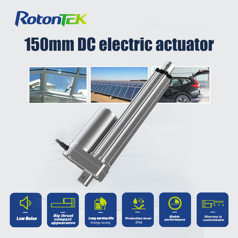
150mm DC electric actuator

Understanding the main function of an actuator is crucial for selecting the right component for your application. As a supplier, we know that a clear grasp of this core function helps you improve system reliability and performance. It allows you to make informed decisions that directly impact the efficiency of your machinery. This knowledge is the foundation for building effective motion control solutions.

My Motion Control Function

The primary function of an actuator is to control motion, converting energy into precise mechanical movement. We achieve this by taking a control signal and translating it into a physical displacement, which can be linear or rotary. This allows machinery to perform tasks like pushing, pulling, lifting, or rotating with accuracy. The reliability of this conversion process is fundamental to the automation of industrial systems. For instance, a motorized linear actuator typically uses an electric motor to create straight-line motion, which is essential in applications from manufacturing assembly lines to adjustable hospital beds. This controlled movement is the basis for automating tasks that would otherwise require manual intervention, enhancing both safety and operational efficiency in diverse environments.

My Force Application Role

Another core function is the application of force, which is essential for tasks requiring significant power, such as lifting heavy loads or pressing components together. We generate this force through various means, including hydraulic pressure, pneumatic power, or electromagnetic principles. The ability to deliver a consistent and controlled force is critical for operations in construction, metalworking, and heavy machinery. Systems designed by electro hydraulic actuator manufacturers often combine electrical control with hydraulic power to achieve high force output in a compact package. This ensures that the actuator can perform demanding jobs reliably, providing the necessary muscle for industrial processes without compromising on precision or control.

My Position Holding Task

A critical, though often overlooked, function is holding a position securely once it has been reached. We are designed to maintain a specific linear or angular position against external forces, preventing unwanted movement. This is vital for applications like stabilizing a platform, locking a safety gate, or keeping a robotic arm in place during a delicate operation. The holding mechanism, whether through mechanical braking, self-locking gears, or fluid pressure, ensures stability and safety. This capability prevents drift and maintains system integrity, which is crucial for precision in manufacturing, medical devices, and aerospace applications where even a minor shift can lead to significant errors or hazards.

Conclusion

Ultimately, the main function of an actuator—to create controlled motion from energy—is a deceptively simple concept with profound implications for both industrial and everyday applications. From enabling complex automation to providing convenience in consumer products, the right actuator solution is key to innovative design and reliable operation. We at Rotontek apply our experience in motor and gear system manufacturing to this essential function, developing components that perform consistently. Our goal is to provide the motion solutions that help our partners and customers turn their engineering concepts into reliable, working reality.

How Much Weight can Linear Actuators Hold?

Understanding the weight capacity of linear actuators is fundamental for selecting the right component for your project. As a supplier, we know that an incorrect load rating can lead to system failure and safety risks. This article explains the key concepts of static and dynamic load capacities. We aim to provide the foundational knowledge needed to make an informed decision for your application.

Static Load Capacity Limits

The static load capacity, also known as the holding load, is the maximum force a stationary actuator can support without being damaged when it is not in motion. This rating is critical for applications where the actuator must hold a load in a fixed position for extended periods, such as in locking mechanisms or support struts. Exceeding this limit can cause permanent deformation of the screw or housing, leading to premature failure. It is distinct from the dynamic load rating and is often higher. When evaluating an actuator for a static application, it is essential to consult the manufacturer’s specifications for the exact holding capacity. For demanding scenarios, an industrial electric linear actuator might be considered due to its inherent rigidity and ability to handle significant static forces without back-driving.

Dynamic Load Ratings Differ

Dynamic load rating refers to the maximum force an actuator can apply or support while it is extending or retracting. This is the most common rating used for sizing actuators and is directly related to the life expectancy of the internal components, such as the screw and nut. The dynamic load is typically lower than the static load because moving parts experience wear and fatigue. The actual achievable force is also influenced by the actuator’s orientation; a vertical lifting application places different stresses on the motor and gearing than a horizontal push. Manufacturers provide life cycle charts that show the relationship between the applied dynamic load and the expected operational life. In systems requiring high force and precision, an EHA actuator, which combines electric control with hydraulic force, can offer a high dynamic load capacity in a compact form factor.

Force Calculations for Actuators

Calculating the required force for an application is a critical step in selecting the correct actuator. The necessary force is not just the weight of the object but must account for the coefficient of friction for pushing or pulling, the angle of inclination if lifting on a slope, and the desired acceleration. For example, lifting a 100kg weight vertically requires a force of approximately 980 Newtons, but pushing the same weight horizontally on a surface with friction requires a different calculation. It is always recommended to incorporate a safety factor, often between 1.5 and 2, to account for unexpected resistance, shock loads, or variations in the system. Proper force calculation ensures the selected actuator will perform reliably and have a long service life, preventing costly downtime and replacements.

Conclusion

Ultimately, the weight a linear actuator can hold is a precise specification that must be carefully matched to your application’s force requirements, environmental conditions, and safety factors. By understanding the difference between dynamic and static loads and considering all mechanical influences, you can make an informed selection. For projects demanding high force and reliable holding in tough conditions, our engineered solutions are developed to provide that critical performance. We invite you to review the detailed specifications for our systems and contact Rotontek to discuss how we can support your specific load capacity and integration challenges.

How Long do Hydraulic Power Units Last?

Understanding the service life of a hydraulic power unit is crucial for planning maintenance schedules and managing operational costs. As a supplier, we know that providing clear, factual information helps you make informed decisions about your equipment. This article outlines the typical lifespan, maintenance needs, and component replacement cycles for these systems. This knowledge supports effective long-term operational planning.

Hydraulic Power Unit Service Life

The service life of a hydraulic power unit is not a fixed number but is influenced by its design, operating conditions, and duty cycle. A well-designed unit operating within its specified parameters in a clean, temperature-controlled environment can often last for decades. Key factors include the quality of components, the frequency and intensity of use, and the effectiveness of the initial installation. Contamination from particles or water is a primary cause of premature failure, making the operating environment critical. For a reliable hydraulic power unit, selecting a model matched to the application’s specific force and speed requirements is the first step toward maximizing its operational lifespan. Regular monitoring of system parameters like pressure and temperature provides early warnings of potential issues.

Hydraulic System Maintenance Requirements

Consistent and proactive maintenance is the most significant factor in achieving a long service life for any hydraulic system. A core requirement is maintaining fluid cleanliness through scheduled filter changes and periodic oil analysis to detect wear metals and contamination. The hydraulic fluid itself must be checked for level, viscosity, and acidity, and replaced according to the manufacturer’s guidelines or based on oil analysis results. Regularly inspecting and tightening connections, checking hoses for cracks or abrasion, and ensuring the reservoir breather is functioning are all essential routine tasks. For systems like an electro hydraulic actuator, particular attention should be paid to the electrical components and seals. A documented maintenance log helps track service history and anticipate future needs.

Hydraulic Unit Component Replacement Intervals

Different components within a hydraulic power unit have varying lifespans and require replacement at different intervals. Seals and O-rings, which prevent internal and external leaks, are common wear items and may need replacement every few years, depending on the fluid compatibility and operating temperatures. Hydraulic hoses should be inspected annually and typically replaced every five to seven years to prevent sudden failure. The pump, as the heart of the system, has a variable life; vane and piston pumps can last thousands of hours, but their lifespan is heavily dependent on fluid cleanliness and operating pressure. Filters are consumables and must be replaced as indicated by a clogging indicator or on a fixed schedule. Electrical components like motors and solenoids generally have a long life but can fail due to electrical overload or environmental factors.

Conclusion

Ultimately, the lifespan of a hydraulic power unit is a partnership between intelligent design and diligent operation. By understanding the factors that influence durability and committing to proactive maintenance, you can significantly extend the service life and return on your investment. For those seeking a system engineered from the ground up for resilience in challenging conditions, exploring integrated solutions is a logical step. We at Rotontek are committed to providing that durability through our compact, protected designs, helping your projects move forward reliably for years to come.