Choose thumb throttle or twist throttle? One-stop analysis

Choosing a thumb throttle or a twist throttle depends mainly on specific needs and usage scenarios. First, we will understand the mainstream throttle market trends, then take a deep look at what thumb throttles and twist throttles are, then make a simple comparison between the two to help you choose which one is more suitable.

Mainstream Throttle Market Trend

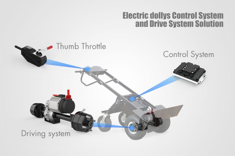
According to the market data in 2023, the global electric dolly market has reached 45 billion dollars, with a year-on-year growth of 15%. The choice of throttle type in the control system of the electric dolly has a very important impact on the overall user experience. The current mainstream market includes thumb throttles and twist throttles. Among them, thumb throttles are favored by many users because of their easy operation and precise control. For example, the thumb throttle of Rotontek products has been widely used in various electric dollies because of its high precision control and durability.

The statistics show that about 60% of electric dolly users prefer thumb throttles, and especially the high-frequency startup and operation in urban commuting and warehouse operations. According to the report by the market analysis company Statista, by 2025, the electric dolly market size will reach 60 billion dollars. The average annual growth rate is about 12%. In this growth trend, the market share of thumb throttles is expected to further increase, and it will become the mainstream choice in the electric dolly control system.
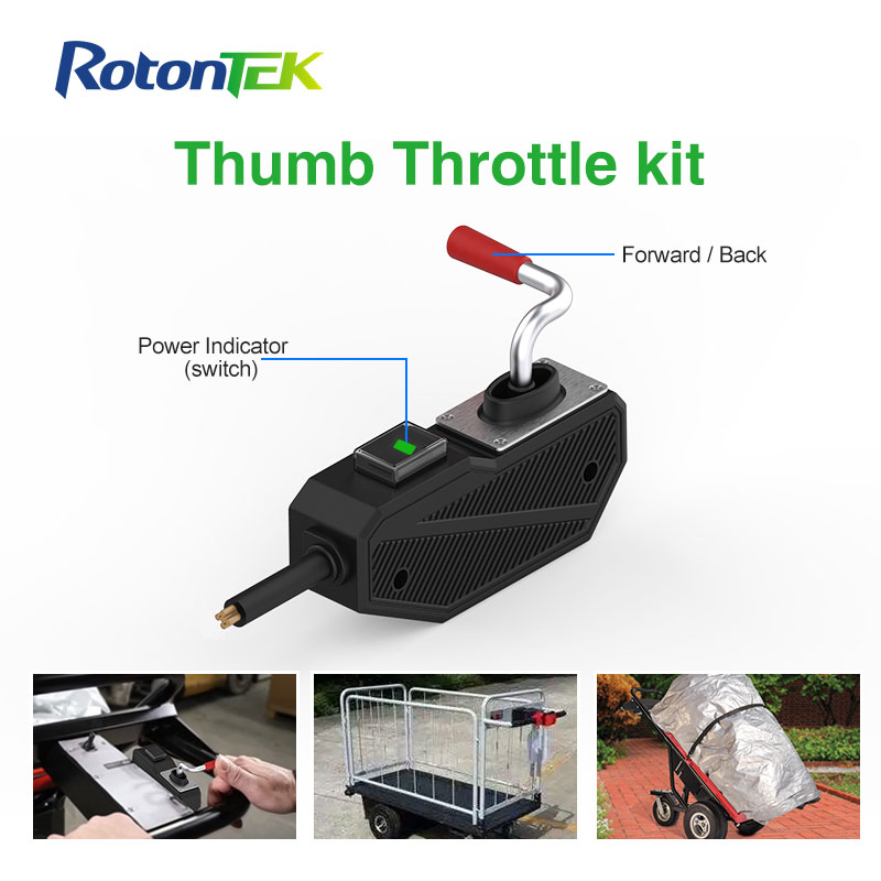
What is a Thumb Throttle

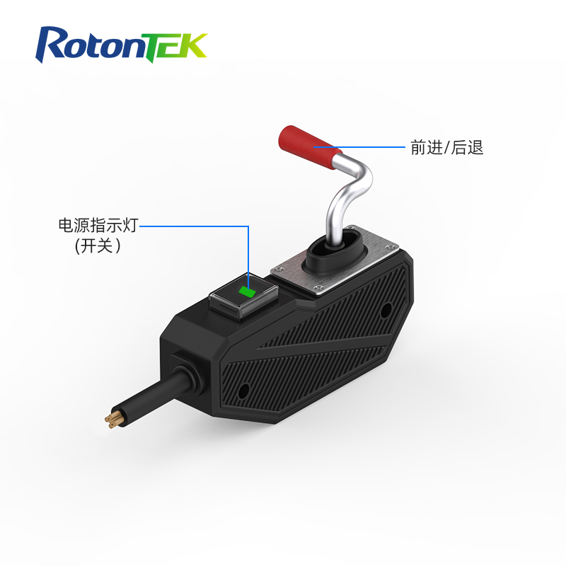
A thumb throttle is a commonly used control device in electric dollies, allowing for acceleration and deceleration by pressing with the thumb. For example, Rotontek’s thumb throttle uses a high-precision potentiometer that provides ±0.1% accuracy in speed control. Data shows that using a thumb throttle in electric dollies improves control accuracy by 30% during low-speed operations. This high precision control is particularly suitable for scenarios requiring frequent starts and stops and precise maneuvers, such as warehouse operations, where using a thumb throttle can increase work efficiency by 20%.

Thumb throttles are usually made of plastic or metal and contain a potentiometer that adjusts the current by changing resistance, thereby controlling the motor speed. According to tests, the average lifespan of a thumb throttle is 5000 hours, meaning it can continue to operate for several years even under high-intensity use. Additionally, a user survey showed that 85% of users find thumb throttles easier to operate than twist throttles, especially noting a 15% reduction in hand fatigue after prolonged use.

Whether to Select Twist Throttle

A twist throttle refers to controlling the vehicle acceleration by rotating the handle. The operational mode of the twist throttle is the same as that of a motorcycle; that way, it feels even smoother and more natural. A crucial benefit of the twist throttle is that it can help reduce hand functions, especially for long-distance drives or high-speed driving. However, the twist throttle is somewhat inferior to the thumb throttle.

First, the twist throttle takes more space of the handle, even approximately 30% than the thumb one, which is not suitable for many vehicle designs that require a small handle. Second, the twist control is less precise in the rotational movement than the thumb throttle in low-speed and micro control, with a decrease in precision to about 15%. Third, for operation needs that require frequent stops and drives, the twist control to be less efficient than the thumb control, which would slow the operation to about 20%. Therefore, in decision-making, one should lean more toward choosing the thumb throttle as a more advanced technology product.

Thumb Throttle vs Twist Throttle

Feature Thumb Throttle Twist Throttle
Price 20-30 dollars 25-35 dollars
Materials Plastic or metal, lighter weight Mainly metal, slightly heavier
Installation Simple, suitable for various vehicles Slightly complex, requires more space
User Satisfaction 85% of users find it easy to operate 75% of users find it natural to operate
Maintenance Cost Low, easy to replace parts Higher, parts replacement more complex
Water Resistance Good, suitable for various weather conditions Average, requires additional protection
Feedback Mechanism Direct feedback, suitable for precise control Smooth feedback, suitable for quick response

Whether to choose a thumb throttle or a twist throttle should be determined based on budget, vehicle type, and usage requirements. Thumb throttles are cheaper and easier to install and maintain; twist throttles are better in terms of natural operation and quick response, but they are slightly more expensive and more complicated to install and maintain. You can refer to the one-stop solution for electric cars launched by Rotontek, where we also recommend thumb throttles, which meet the needs of most users with their higher cost-effectiveness and convenience.

What are the advantages of thumb throttles

Benefits of thumb throttle

The apparent simplicity of thumb throttles, operational efficiency can be dramatically improved by their use. Where thumb throttles are used for factory workers the productivity increase is 20%. This means the amount of products produced per hour rises by a significant amount, directly influencing how many people are serviced on the production line. They are also ergonomic in design, reducing worker fatigue when used over a long periodTraditional handle-style throttles are not only inconvenient to use, but can lead to wrist fatigue.

By contrast thumb throttles allow workers to remain in a natural posture when operating machinery, thus reducing discomfort at work. In some highly precise operations where operators need to control the speed or direction of a machine precisely, the high sensitivity of thumb throttles is invaluable. With thumb throttles, compared with traditional throttles, operators are much less likely to overshoot the mark, ensuring a smoother and more accurate handling process.

With a simpler structure than traditional throttles, and lower failure rates, thumb throttles require about 25% less maintenance cost. In equipment-intensive factories, this is especially important: a considerable amount of maintenance cost is saved as a result. Since operators can promptly respond in emergencies while thumb throttles are so simply designed, accidents are cut back. Safety reports from factories show that as a result of using thumb throttles, the incidence of workplace accidents in these workplaces fell by 12%.

Tips for Using Thumb Throttles

Grease and dust can affect the sensitivity of the throttle and regular cleaning can ensure the normal operation of your equipment. Regular cleaning of thumb throttles can reduce your error rate in operations by 15%. Some thumb throttles have multiple modes, high speed mode and low speed mode for example. Understanding their functions and skillfully using these modes can control speed according to different tasks and raise job efficiency.

Using low speed mode for transportation of heavy loads ensures safety, while during no-load operation using high speed mode can raise efficiency. Long periods of incorrect posture can be harmful, leading to finger cramps or other injuries. It is recommended that workers take breaks from time to time and adjust their finger posture so they don’t suffer longue duree strain. In low temperature environments, the sensitivity of the throttle may decrease.

Comparison of Thumb Throttles and Other Throttles

Thumb throttles are designed to avoid fatigue, letting the workers operate with a more relaxed hand position. As a result of this ergonomic advantage operators using thumb throttles suffer from 30% less hand fatigue after long periods of operation. Because of their simpler design and fewer moving parts thumb throttles have lower maintenance costs.


Feature Thumb Throttles Hand Throttles
Precision Control 15% higher accuracy Standard
Ergonomics 30% less fatigue Higher fatigue
Maintenance Costs 25% lower Higher
Safety 12% fewer accidents Standard
Durability (Years) 5 3.5

Throttle Improvement Effects Study of Thumb Electric Dollys

Electric dollys with thumb throttles can easily control speed and orientation. The error rate when moving can be down to 15%, which also makes narrower paths more advantageous for thumb throttles. The tedious hand work of throttling actually extends time, thus reducing efficiency.

Because of precise control characteristics, electric dollys fitted with thumb throttles consume less energy during acceleration and braking. The average energy consumption per electric dolly with thumb throttles drops by 10%, which is crucial for control of manufacturing costs. With thumb throttles, electric dollys can rapidly respond to emergencies and accidents befalling a very low number. Thumb throttles feature a robust structure compared to tradition throttles.

How to troubleshoot brushless DC motors failure? Correct steps

The brushless direct current motor now enters its primary era with the development of intelligence, high performance, low maintenance, and low noise and becomes the first choice in an entire world of industrial applications. According to the data published by Market Research Future, the global BLDC motor market was worth $8.72 billion during the year 2022 and is expected to be worth $16.29 billion by the year 2030, courtesy of the annual average growth of 8.1%. This boom also owes its growing demand to the use of electric vehicles, household appliances, and industrial automation.

In using and maintaining brushless DC motors, the most crucial thing is troubleshooting through which one will guarantee motors’ service life. Significant differences remain between different types and models of brushless direct current motor units concerning the electrical systems, sensor and signal causes, and mechanical components. We will discuss a proper electrical inspection, sensor and signal inspection, and mechanical inspection. We explain how to make the right service for your brushless DC motor according to the required parameters in the corresponding differences of various types of motors.

DC Motors Electrical System Diagnostics

Check Power Supply

Before anything else, before troubleshooting, you should check for the right voltage and current values on the motor. It is better to measure the values with a high-quality multimeter. If it is a motor of 24V rating, then this 24V should always be supplied to the motor. Any deviation from this indicates an incorrect work by power supply unit or by the wiring. It must have a good quality cable as loss of voltage through it will be less in good cables. Different motors will require different voltage and current values, you must check on your motor’s datasheet.

Inspect Connections

It may be loose connections or damaged connections which cause sporadic power outage issues or shaky operation. Go ahead and check out all the lines and connectors carefully, looking for broken, corroded, or physically damaged ones. If you see any loose connections, tighten them or replace damaged wires. You could also remove corrosion quickly with an electrical contact cleaner at this time. The part of a brushless motor that will not give you problems is going to be bought from a top-quality brand supplier such as Rotontek.

Test Controllers

In order for DC brushless motors to work well, they are provided with motor controllers. The controller will be considered faulty if, through the diagnostic tools, you have confirmed that there are no error codes or bad control signal irregularities. A defective controller will show symptoms in the way of sharp speed variations or the controller will not start at all. Another means that can be used is to plugin a verified good controller to check if the fault comes from the controller or not. The fact is that sometimes the firmware was outdated, so we can solve it by updating. The control is never so 100% reliable, so the problem might sometimes be a result of the specific motor model.

DC Motors Sensor and Signal Evaluation

Hall Sensor Check

Detection of the rotor location is one of the main functions of Hall effect sensors in the operation of any motor. Turning the motor manually tests each sensor and notes the outputs of each sensor. Each sensor should provide a clean periodic signal. The integrity of the waveform can also be verified on the oscilloscope. If a sensor fails as it should, it could be defective; replace it. Always ensure that the sensor alignment and connections are in place. More expensive motor types will use better quality/reliability sensors.

Signal Integrity

Wear and EMI investigation of signal cable. Shielded cable reduces noise and thus provides clearer signals. Poor condition signals will cause miscommunication with the motor and controller which result in erratic motor functioning. Check the nearby EMI sources and relocate or shield them. Check the security of all signal connections. Different motor models will have different susceptibilities to EMI, and this should be taken into account.

DC Motors Mechanical Inspection

800W Encoder DC Brushless Motor features

Physical Damage

It is not necessary to dismantle your engine to know the condition of your engine-the exterior has much to say about it. The most important things to look for are severe cracks, dents, or damage that is visible and reduces the effectiveness of the motor. The other point is to make sure that it is firmly mounted and does not have any blockage in its cooling vents. Since most of the time damage occurs physically, also consider motors with heavy-duty exteriors, which rarely have cracks, dents, or other visible marks, to augments application considerations.

Bearing Condition

Turn the engines motor shaft by hand and listen for odd, squeaky noises. The bearings should normally turn without struggling, and they make no sound. The bearings are grinding or rolling unevenly, indicating the need for lubrication or replacement with the same quality grease as specified by the motor’s manufacturer. Ensure that bearing is not over-lubricated since it attracts dust and other debris, which are detrimental to its life expectancy. Safety and reliability of bearings differ considerably in different motor types.

Noise Analysis

Motor testing involves spinning the motor and listening for abnormal noises like whining, clicking, and grinding. Such noises may signify mechanical problems including worn bearings and misaligned mechanical parts. A look at the rotor and stator surfaces will tell if there has been any physical contact or signs of wear. Different manufacturers make different noise levels and mechanics of faults in motors. Therefore it is possible to know what the problem might be by comparing the two.

Factors to Consider for Different Motor Models

In troubleshooting brushless DC motors, you must apply different models of motors. Ideally, buy them from a giant and trusted name like Rotontek. They manufacture extremely high-efficient, noise-free brushless motors having a very long service life, specifically engineered for automation needs. At the same time, you can save most of the costs. An electric and mechanical reliability as well as even whole motor performance vary to a very great extent between different manufacturers, and some of the value points worth evaluating include:


Different motors may demand different levels of voltage and current. Ensure that the appropriate supply matches every model. Some motors must work with other controllers that are supposed to use specific motor performance features to their best. Thus, the controllers should always be checked when working with such motors.


Bearings from various producers really impact the longevity of a motor, especially those bearings that are of higher class with no extra attention to servicing, while the housing should also be such that it holds the parts of the machine from getting dust, dampness, and physical impact.


The quality as well as the location of the Hall effect sensor; with a better quality sensor, it is attached less failure modes, and further provides a more accurate estimation of motor position- they will also be beneficial in its performance. It can be relative noise as well, which is produced by different models of motors and should be considered while purchasing one for applications where sound generation is not desirable.


The motor can be everything made of easily accessible components like bearings and Hall effect sensors. At the same time, components should not wear out rapidly to be replaced. That way, should any of the motor components fail, it can be easily and timely replaced with a reserve.

What Is a Motor Controller and How to Choose the Right One?

A motor controller adjusts speed with PWM, includes overvoltage protection, uses closed-loop feedback for torque, and features regenerative braking.

Introduction to Motor Controllers

Motor controllers are critical devices used to operate electric motors in all sorts of industrial vehicles, with motor controllers being used in everything including but not limited to unmanned patrol cars, motors in electric tugs, electric cleaning vehicles, electric sweepers, electric floor scrubbers, golf carts and electric sightseeing vehicles.

The speed, torque and direction of the motor are all regulated by the motor controller. Motor controllers are able to interface with all different types of motors, each with individual technologies and applications. When fitted properly, the motor controller can provide the most precise control of the motor. This value can range from a simple DC motor, to a more complicated brushless DC motor.

Definition and Functionality

A motor controller is an apparatus that influences the parameters of motor operation. Among other things, it determines the magnitude of input power for the motor in accordance with desired speed, rotation direction, and torque.

The main functionality of motor controllers includes starting and stopping the motor, moderating its speed by varying the voltage or current and protecting against the common faults such as overvoltage, undervoltage, and overheating. Finally, the most sophisticated controllers feature things like regenerative braking, which recovers the energy rather than turning it all into heat at the breaking resistor.

Drive Controller ID500

Types of Motor Controllers

Motor controllers can be broadly classified into several types based on the motor they are designed to control. Each type has unique characteristics tailored to specific applications and motor types.

Brushed DC motor controller

This is a simple device used to control a brushed DC motor. The brushed DC motor is found in more modest industrial vehicles because of the ease at which the motor can be controlled and it relative low cost. Brushed DC motor controllers use Pulse Width Modulation to control the speed and direction of the motor.

Brushless DC motor controller

These types of motor controllers are used with Brushless DC motors which are commonly used in applications where high efficiency and reliability is critical, for example, electric floor scrubbers and sightseeing vehicles. The controller has sophisticated algorithms as the commutation of the motor is done electronically.

Stepper motor controllers

Stepper motor controllers use a method where the full rotation of the motor is divided into equal steps. These are best used where precise position and repeatability is important. These motors controllers can be used to control robotic functions on the industrial cleaning vehicle, which will require exact positioning and movements.

AC motor controller

This type of motor controller, also known as an inverter can be used with an AC motor, which is often used because of its inherent robustness and power of the motor. The AC motors controller can convert power from the batteries into the power required for the AC motor to run. The system can provide variable speed control, which is also a requirement for some applications.

Components of a Motor Controller

Motor controllers consist of a set of crucial components that work in unity to regulate motor performance of industrial vehicles. These include the power supply, control circuitry, and feedback system. Each of the elements is fundamental for ensuring the appliance runs efficiently and reliably in such applications as unmanned patrol cars, electric tugs, electric cleaning vehicles, electric sweeper vehicles, electric floor scrubber, golf carts, and electric sightseeing vehicles.

Power supply

Firstly, the power supply is the core of the motor controller. It supplies the necessary electric energy for the functioning of the motor. In the specific case of industrial vehicles, it usually involves a battery with a large capacity that offers a steady and reliable supply of energy.

Control circuitry

Control circuitry or the motor controller’s brain is responsible for processing the input signals and, further, appropriately adjusting motor operation. It often involves microcontrollers or digital signal processors, which empower and execute control algorithms.

Feedback system

The third type of motor controller component includes feedback mechanisms responsible for offering real-time data regarding motor performance. As a result, the controller can make any necessary replacements for appropriate function. 

Factors to Consider When Choosing a Motor Controller

In particular, selecting a proper controller is crucial due to a range of reasons. First and foremost, the chosen device should help the vehicle achieve its optimal performance. Second, it is necessary to remember that a well-chosen controller can add to the long-term efficiency and lifespan of the motors. For example, the wrong controller will not provide the required voltage and/or current to the motor, thus failing to motor controller to be used with the right one.
Motor Type

First, one needs to consider the motor type when choosing a controller. For instance, brushed DC motors, brushless DC motors, stepper motors, and AC motors require an accordingly suitable controller. In other words, the brushless controller cannot be used with the brush motor. Relatively few controllers are universal in nature, meaning that their manufacturers offer them for use with all motor types.

Drive Controller For DC Brushless Motor ID200

Voltage and Current

The second consideration is the controller’s capability to provide the needed voltage and current to the motor. It is perhaps the most basic of the requirements because during operation, the motor requires an adequate amount of voltage and/or current. Thus, the controller one selects needs to be tested to ensure that it can purely provide the needed amount in all circumstances. The controller’s inability, or a lack of necessity to increase or decrease the current, can create substandard conditions for efficient operation.

Environment

The environmental conditions at which the controller is to be used also important. In particular, the place of operation should not be too hot, cold, humid, dusty, etc. This is because those conditions will impact the long-lastingness of the controller’s lifespan or render it otherwise defective.

How to correctly install the motor? Precautions for motor installation

Understanding Installation Requirements

Electrical Specifications Compliance

It is essential that the motor meets all electrical specifications for long-term motor life and operational safety. You want the electric supply to match the motor’s voltage, current and power requirements so as not to overload circuits. For example, if a motor is listed as 24V and capable of up to 300W, make sure that the electrical arrangement can supply 24V, and that the engines can draw the peak current without tripping the circuit.

Space and Mounting Considerations

It is to be noted that the working space for the physical set up needs to dove tail well with the size of the motor and associated hardware without any distorting or over crowdedness that will result in the over heating and lowered efficiency. Keep at least 3 inches of free space around the motor for airflow to allow the motor to stay cool as the airflow through the motor is critical to not cause the motor to overheat and exceed the proper operating temperature. Mounting should be free from oscillation, the mounting surface also will not be waving, and deformation, which can enable misalignment and wear.

Environmental Factors

The surroundings wherein you operate the motor too, can also have a huge impact on its performance. This is because motors should be situated in places with not much dust, moisture, and there should be no too hot or cold climates. If a motor operates in a humid environment, for example, the motor must have at least an IP55 rating to provide the required protection from moisture and from the ingress of dust particles.

Understanding Installation Requirements

The right tools and equipment It is very important to gather all the tools and equipment you need before the installation process starts. The normal set of tools for motor installation would be a multimeter, set of wrenches, screwdrivers, wire snips and possibly a soldering iron for good electrical connections. Be sure to have the proper nuts and bolts and hydraulic motor mounts specific to your motor weight and installation per the motor installation guide. A torque wrench can also be really handy for ensuring you apply the correct amount of torque to bolts to avoid from overtightening or under-tightening, which can cause a whole host of mechanical failures.

Step-by-Step Installation Guide

The subject of motor mounts are the foundation of the reliable performance of a drive. Start by placing the motor at a surface flat and as still as possible where it will be installed. Make sure the wheelbase of the mounting area matches the mounting area of the motor to prevent misalignment that may cause mechanical wear or vibration. Check and make sure motor sits to level with a level tool Mount the motor with the appropriately sized and load-rated bolts .

First, consult your motor model-specific wiring diagram. Attach electrical power cable to the corresponding terminals — L1, L2, L3 for a three-phase motor or + and -for a DC motor. Connect the wires using wire nuts or terminal blocks and make sure each connection is secure, then test and double check the connections for shorts or open circuits by using a meter running from the 5V wire to the ground wire.

With the motor secured and wired, be sure to inspect the entire assembly for any loose components or tools in the vicinity. Inspect how easily the motor spins, it should offer a sense of resistance free rotation if there is a bind or an abrasive sound that shouldn’t be there it is a sign of an issue with it being square or there might be something foreign or wrong with the motor. Briefly power on the motor for a test run to ensure that it functions properly and responds as expected to your control inputs.

Post-Installation

Maintenance Tips for Newly Installed Motors

Performing regular upkeep helps to lengthen the life of your engine and keep it running at its best. Begin by scheduling regular inspections, paying close attention to inspecting connections for tightness and/ or signs of wear or corrosion. Follow the manufacturer’s standard for the type of grease or oil to be used but lubricate moving parts every six months. You should also periodically check the insulation resistance of the motor, especially in moister or dustier environments, since the purpose of this test is to detect electrical faults.

Troubleshooting Common Installation Issues

downtime you face. This can lead to a variety of common issues from overheating, poor performance or excessive noise or can also be the result of bad drivers, poor fitting or flawed components. If the motor will not start, inspect your electrical connections and make sure all safety switches are in the engaged position. Since overheating can be a sign of either overloading the motor or poor cooling, you should check if the load is within the motor’s rating and if there is proper air ventilation. For mechanical noises or vibrations, check if motor is well mounted and alignment is ok.

How to Choose the Right Motor Wheel According to Different Usage Scenarios

Understanding Motor Wheel Specifications

Motor Type and Power

Understanding the significance of Motor Type and Power ratings are vital pointers in identifying the correct motor wheel. Brushless motors in the same family as the ones from Rotontek in their LTD03 and DL210 model, are know for their power efficiency and don’t need regular maintenance. As there are no physical brushes in brushless motors, wear is eliminated, the effect of which is always driving performance and enabling a much longer service life. Motors of this type deliver power anywhere from 250W to 2,500W, covering everything from the lightest personal mobility aids to the heaviest material handling equipment.

Wheel Size and Load Capacity

The motor’s wheel size and its load capacity are key factors that must be considered to match a motor wheel to the type of vehicle it is intended for.

1KW Brushless Electric Driving Wheel DL1000-1-29 give you generally heavier duty larger wheels, these are perfect for rough terrains, whilst the LTD02 Permanent Magnet Brushless Motors Electric Wheel Drives for indoor environments and smooth surfaces.

Application-Specific Considerations

For Material Handling Equipment

Material handling equipment such as forklifts or electric stackers require a serious problemolving effort to determine the suitable motor wheel with regard to towing weight and speed. Like the DL210 Brushless Electric Drive Wheel, which has a power output of up to 850W with load capacities of up to 1,200 kg per wheel – making it perfect for applications where heavy loads need to handled with precision and poise.

For Mobility Aids

Picking motor wheels for wheelchairs and mobility scooters are crucial as you need to check out their noise, suitable smoothness, and battery-efficient designs. The LTD02 and LTD03 is the only model of its kind with an ultra-quiet operation, an important factor in areas where quiet, such as homes and health care facilities, is required. The cart with its low-noise design – below 50dB – and more comfortable, smoother drive is key to improving user comfort and mobility.

Environmental and Operational Factors

Indoor vs. Outdoor Use

Proper selection of motor wheel(s) goes a long ways in terms of performance and sustainability, depending on the environment. Being outdoors, the motor wheels have to be really reliable in their resistance to elements such as water, dust and so on The IP54-protected motor wheel in version DL1000-1-29 is developed for use in damp and dusty locations and operates without any problems even under these adverse conditions. This ingress protection Class 4 is a necessity for outdoor applications, like handling equipment and mobility aids, without forfeiting in wet weather.

There are also considerations that come into play for applications that are indoors such as noise reduction and non-marking tires. LTD02 : With a particularly quiet operation and precision controls to prevent any damage to indoor flooring, this model offers a notable alleviation in disturbance in settings such as hospitals and office buildings.

VS

Technological Advancements and Innovations

The motor wheel sector has progressed significantly, with these advancements greatly benefiting in terms of ease of use. Used in mobility aids and material handling equipment, electromagnetic brakes provide these devices with excellent stopping power and reliability (see LTD02). This yields instant brake response, as well as near-perfect balance and virtually zero wear, significantly enhancing stopping capability without resorting to more literal contact patches as used by traditional braking systems.

In addition, precision gears are essential for achieving high-performance output in small design packages. Each DL210 Brushless Electric Drive Wheel incorporates finely-honed gear mechanisms for quiet power transfer, so it is a good fit for those settings that prefer quieter operation. The spinning of these gears increases output and torque to deal with the increasing load, showing the extent of how refined modern engineering is used to improve the fundamental operation of motor wheels.

How to Pair Your 1kW Brushless Motor with the Right Controller

Technical Specifications and Requirements

Detailed examination of the 1kW Encoder DC Brushless Motors

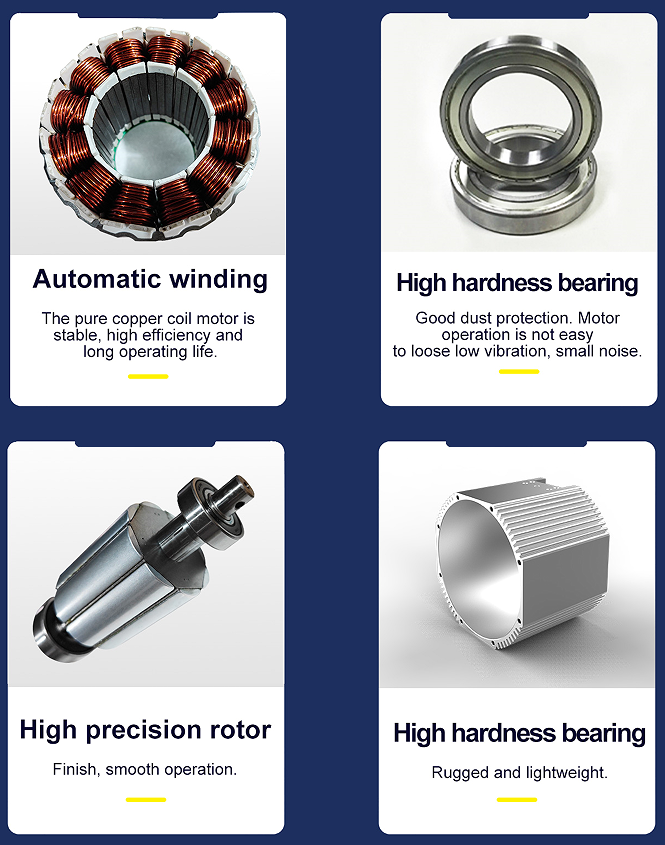
The 1kW Encoder DC Brushless Motors feature automatic winding end high precision rotor which provide good performance and reliability. This type of motor has an aluminum casing which assist sin effective heat dissipation and as such, can function in different environmental conditions. It is also rated at 1kW although it may have different operating voltages as may be required, normally at 24V, 43V, or 48V. It also provides smooth operation to ensure less wear and as such increasing the life span of the motor.

Best DC Brushless Motor for 2024

Capabilities and features of the ID200 Series DC Brushless Wheelchair Controller

The ID200 Series Controller is a suitable choice for controlling motors. It is a programmable controller and can as such offers a perfect match for this type of motor. It has a wide range of operating voltages between 24V and 48V, and it is suitable when the requirements are as those of the motor. It offers full range of programming options such as speed before and after threshold and the exact level of torque, as well as 8 different selections on the running direction. This can be matched to any motor type using the controller’s software. This is critical where precise controlling is required such as in wheel chair mobility or in automated vahicle sytems.

Step-by-Step Guide to Connecting Motor and Controller

Physical setup: connecting motor wires to controller terminals

The 1kW Encoder DC Brushless Motor must be properly connected to the ID200 Series Controller. Turn the power off first to avoid any electric shock. Then, locate the three main wires from the motor: red, black, and blue. These correspond to the three phases of the motor and must be connected to the respective terminals on the controller, which are also typically labeled red, black, and blue. Use a screwdriver to secure the connection. Do not forget to check if the connection is proper using a multimeter. The watch for the short circuits will allow avoiding possible damage to the motor due to the electric surge. Configure the settings as necessary to ensure the continuity of the connection. Operating the motor without such testing might not allow proper work of the appliance and lead to unexpected failure.

Configuring controller settings for optimal motor performance

Following the proper connection of the motor and controller, adjust the settings of the ID200 Series Controller to ensure the most effective operation of the 1kW motor. The software interface can typically be accessed from the PC or an attached programming device. First, configure voltage and current to match the motor specifics. This often means setting both the voltage and current cap at either 24V, 36V, 48V or any other option, depending on the input parameters. Make sure that the current limit is acceptable to prevent the motor overload. Adjust the acceleration and deceleration rates to ensure smooth operation of the motor, minimizing the mechanical pressure on its parts when the motor starts or stops. Configure the encoder settings to correspond with the specifics of the motor’s encoder. The latter is important for the feedback of speed and position information. It might be necessary to test the settings multiple times while testing the motor under the load to ensure that desired settings are achieved.

Step-by-Step Guide to Connecting Motor and Controller

Comparison of performance when pairing the ID200 Controller with the two different 1kW motors

When connecting the ID200 Series Controller to either of the two versions of the 1 kW motors, there will be noticeable differences in performance metrics, such as delivered torque and speed control. Specifically, the first motor, which has an automatic winding, will experience smoother acceleration curves and require less energy for various loads. Meanwhile, the second kind of motor, which has a rotor of higher precision, might deliver a significantly larger level of speed precision, which would be useful in cases where the speed of the motor is supposed to be manipulated in a more calculated way, such as when turning some kind of a mechanism with this motor or positioning it to perform a certain function.

VS
1KW Encoder DC Brushless Motor(With electromagnetic brake)

Discussing various application scenarios

The controller plays a vital role in ensuring that the intended operation can be carried out with as little waste of energy as possible. The more precisely the motor can accomplish the task, the lesser amount of energy it will waste. It is especially important in the case of unmanned cleaning vehicles, which are controlled by the controller to navigate places with a lot of obstacles, such as cafes and restaurants.

Drive Controller For DC Brushless Motor ID200 application

Maximize Efficiency with Our 1.8kW Brushless Motor and Controller Combo

Enhancing System Performance with the 1.8kW Brushless Motor

Overview of 1.8kW Motor Capabilities

The 1.8kW brushless motor is built around a highly-efficient silicon steel core, which allows it to work powerfully while wasting as little energy to the sides. Capable of working with a range of voltages, including 24V, 36V, and 48V, the motor reaches a peak power output of 1.8kW. Its model is capable of connecting with speeds of up to 4000 RPM, which allows for precise and powerful control while working in the environment where it is most needed.

1.8KW Encoder DC Brushless Motor

Setting Up the Motor for Various Operational Modes

To make sure that the 1.8kW motor is used to its full capacities, it should be set up properly. The first thing is to select the necessary voltage depending on the power output required by the device. After that, it should be connected to the corresponding controller – in this case, to ensure the best connection, the 2kW model can be used. Operation modes can be then switched using the PWM input mode, allowing the motor to work from low-supplied current/torque and confer energy to high-precision power.

Mastering the 2kW Brushless Controller for Optimal Efficiency

Step-by-Step Installation Guide

2kW brushless controller should be situated in a place where it is protected from heat and debris. The positive terminal of the power supply should be connected to the positive terminal of the controller, while the negative terminal of the power supply should be connected to the negative of the controller. Motor leads are connected to the controller, and the loading tightened. In order for the controller to work properly, it is programmed through the onboard programming interface to a certain speed limit or number of rotations that it can facilitate. Acceleration and deceleration curves are also set by the means of the on-board programming interface.

Configuring the Controller for Maximum Performance

The process of configuring the controller in order to guarantee its optimal functionality is closely linked to adjusting specific settings, which depends on the operational specificities of a certain implemented application. In particular, the maximum speed and torque limits need to be pre-set with the help of a programmable module. In order to ensure the maximum efficiency of the controller, its PID settings are adjusted. Finally, the 2kW brushless controller contains a diagnostics tool, which can be used to monitor specific performance settings in order to adjust the modes of operation if certain deviations are detected.

Synergizing the Motor and Controller for Enhanced Output

Ensuring Compatibility and Performance Between Devices

To ensure compatibility, one needs to verify that the controller’s output matches the motor’s rated voltage and power requirements. In order to test the controller, it is possible to use diagnostic tools to test the controller’s response to motor inputs. It is also possible to test the motor at different speeds and operations to see whether there are any differences of controller’s performance. Performance optimization relates to adjusting the parameters of the controller, such as max current and RPM limits, to ensure that the controller can handle the load and various operational conditions will be adjusted to this specific task.

Real-World Examples of System Configurations and Their Benefits

This type of combination may be applied in different real-life project, which include automated material handling systems permitting the controller to precisely position the load and handle it with higher efficiency. If the same combination is used in personal transportation and the controller is mounted in an electric vehicle, it will ensure more precise acceleration control and efficient energy use, which will allow the car to drive larger distance.

Comparative Analysis of Different Motor and Controller Pairings

Comparing 1.8KW Encoder DC Brushless Motor with 2kW Controller

The combination of the 1.8KW Encoder DC Brushless Motor with the 2kW controller allows an application-specific approach when precise speed and torque control is required. In automation and robotics, such a solution would boost overall precision due to the high torque at low RPMs and would enhance the level of energy efficiency by optimizing the use of power. However, as motor control is enhanced only for speed consistency, it might require additional adjustment to effectively address changing load conditions, and the increased precision of the setup would potentially heighten initial costs of the solution.

Comparing 1.8KW Encoder DC Brushless Motor (With electromagnetic brake) with 2kW Controller

The combination of 1.8KW Encoder DC Brushless Motor with electromagnetic brake with 2kW controller provides additional safety features necessary for applications where a quick stop is required, i.e., automated guided vehicles or heavy machinery. Thus, the proposed setup would sustain optimal performance while guaranteeing complete stopping due to the use of the electromagnetic brake. At the same time, it would make the controller setup more complex due to the need to ensure synchronized operation of the entire system. Overall, the necessity of maintaining the conditions of the brake for it to function effectively in the long-term could potentially result in the increased level of maintenance compared to the solution proposed above.

VS
1.8KW Encoder DC Brushless Motor(With electromagnetic brake)

How to do the wiring of 1.8kw BLDC motor ? Full Proper Wiring Connection

Introduction To 1.8kW BLDC Motor Wiring

BLDC Motor Technology Overview

Brushless DC(BLDC) motors have been invented as a somewhat modern innovation in the field of electric motors, known for its substantial efficiency and reliability enhancement. Their service life becomes much longer than that of their predecessor, the brushed motor. This is achieved due to the electronic commutation system instead of mechanical brushes, which implies virtually to no mechanical wear and ensures precise control of the speed and torque of the motor. BLDC motors are often used in the machines that require precise speed control such as electric vehicles, HVAC systems, and drones.

1.8kW BLDC Motor Specifications and Features

The 1.8kW BLDC motor is powerful with an 1.8kW nominal power output. It is able to develop high torque on a broad range of speeds. It is designed to work around 48 volts DC with the peak efficiency greater than 85%. It has a rugged design that allows for a continuous operation under changing load. It is also has thermal protection, which allows to work at a lower level of power to avoid overheat. All this features make it a perfect motor for industrial purposes and powerful consumer products.

Step-By-Step Guide To Wiring A 1.8kW BLDC Motor

1. Gather necessary tools and materials:

If you wish to establish a connection of 1.8kW BLDC motor, you will need to have specific tools. These include wire and soldering equipment, such as wire strippers and screwdrivers, as well as electrical tape, multimeters, and soldering irons. 

All the tools and materials are to have the correct rating, which means that you need to guarantee that all of them are adapted to the proper voltage and current conducted by your BLDC motor. In addition, 1.8kW motor commonly utilized 14-16 gauge wire.

2. Prepare the Motor and Wiring Area:

Before you start wiring, you must make sure that the motor and the control unit have been correctly configured and are ready for installation. The first step towards this is to mount the motor on a clean, dry and stable surface so that it cannot move when the assembly is functioning. Remember that it is also important that you have some good lighting so as to avoid any mistakes regarding the connections. Following this, you must have a very careful look at the control unit so to check whether there are any signs of damage or wear. If you see that the heat sink or another other contact surface is dirty, you must clean it with a cloth and then apply thermal paste to the high-temperature areas so to improve thermal conductivity and extend the life of the components.

3. Connect the Motor Wires:

To connect a brushless DC motor to an ESC,firstly, identify the motor phase wires, which are usually internally labeled as U, V, and W. Connect these phase lines to the corresponding outputs of the ESC in the same order.

If you want to make a permanent connection, solder the phase wires to the ESC using a soldering iron. But if you prefer a removable setup, connect these wires with a crimp connector.

For the motors having Hall sensors to provide the rotor position feedback, you should plug these sensors into the designed service ports in the ESC. Make sure that these connections are not only tight but also correspond correctly. Otherwise, the phases might be misaligned and cause the motor to work inefficiently or even become damaged.

4. Test the Connection:

Before running the system, you should firstly use an multimeter to ensure that it has continuity. Connect the power and start a simple low-power test run. Pay attention to whether the motor is abnormal, such as: make a harsh or abnormal sound, or stop run. Then adjust the wiring and load to avoid the abnormal phenomena and make the motor run smoothly. Then you can use a multimeter to measure the impedance between the motor’s three phase lines to know whether it is proper connected.

5. Precautions for Wiring Power Supply:

When you connect the power supply, you must determine whether the power supply can drive the motor. You must also use the power and motor wires appropriate to deliver the maximum current you want to provide. You must also consider the EMI related to the power lead, this interference may affect other electronics in your system. In this cases, you can choose a higher quality wire and install an EMI filter to get a better interference abatement effect in the process of motor operation by the same power supply and the same wiring.

After the motor is running, you can use the oscilloscope to get the total voltage waveform to see whether the connection is correct by observing the phase voltage. If the connection is correct, the total voltage waveform is asymmetric.If the connection is not correct, there will be high impedance state in the waveform of the straight line of the total voltage waveform.

Phase voltage waveforms with correct wiring configuration

Troubleshooting Common Wiring Issues

Diagnosing Electrical Connection Problems

Electrical connection problems with BLDC motors reveal themselves in unexpected motor behavior such as rough start or failed start. To diagnose such problem, which seems to be common, you can check all the wires on the subject of tightness and alignment. Using a multimeter, test wires and connectors one by one on continuity. If the continuity is interrupted, there is possibly a faulty wire or a connector, both of which should be replaced. Also, make sure to verify that the motor phases are all correctly connected, as a mismatch could cause severe performance problems. This should solve any most common problems with motor behavior.

Dealing with Wiring Overheating

The heating of the connected wires can pose a serious safety hazard as well as reduce the performance and life span of the motor. This typically occurs due to insufficient wire gauge or a poor connection. In order to fix this issue, the user should first verify if the used wire gauge is suitable to the current load. If it is not, you will have to switch to a thicker wire. Also, make sure that the connections are made tight and there is no sign of corrosion, as poor connection can add to the overall resistance and therefore to the heating. Also, consider installing a radiator or a cooling fan to compensate for the heating.

Solutions to Vibration and Noise Problems

The vibration and noise are common for a poorly installed or malaligned motor. To reduce it, make sure that the motor mount is stiff and all its screws are tight. Also attach a vibration damping material between the motor and the mounting surface. If the sound or vibration persists, check whether the motor and the controller is maligned and realign them. Balancing the rotor of the motor and using elastomeric couplings help to reduce the vibration and noise of controller greatly, which leads to increased operational smoothness and reduced component wear.

Comparative Analysis of Different Models

1.8KW Encoder DC Brushless Motor


VS

1.8KW Encoder DC Brushless Motor(With electromagnetic brake)

Key Operational Differences Between Models

The operational differences between the 1.8KW Encoder DC Brushless Motor and the same motor with the electromagnetic brake show that adding the brake can help with performance and safety. The motor alone works efficiently under normal conditions, with a very high level of control due to the encoder. However, the version with the brake will be safer, as it can be stopped immediately in case of a malfunction or even power failure.

The efficiency of the brake-equipped model is typically slightly lower due to the need to spend more power on the brake. However, this tradeoff is usually acceptable as the added control can be critical for stopping robots or emergency systems in automotive applications.

Adaptations in Wiring for Different Use Cases

As have been mentioned earlier, wiring adaptations differ one for another depending on their application. To be more specific, in a relatively basic consumer application, such as a home appliance, the use of the standard model without a brake is likely to be preferable. The reason for that is relatively clear: the use of the standard model is more straightforward and benefit from the point of view of cost-effectiveness. The situation is reversed in the case of any type of industrial application. The model electrical wiring as per the brake-inclusive model cannot under any circumstances be overlooked. The use of this model depends on the simple fact that in many industrial applications, safety measures cannot be compromised, and the brake is, therefore, indispensable. However, this comes with a significant increase in the complexity of wiring. Due to this complexity, the wiring must be carefully planned and executed.

If in this case,the wiring must effectively integrate the additional safety circuits, which in turn implies the necessity of a relay or a brake controller that can handle the extra current and make sure that the brake engages, and disengages at the right moments.

Tips for Customizing Connections Based on Model

In order to properly customize the connections for either model, it is essential to understand the needs of the application and the exact operations of each type of motor. For the standard motor, the primary system that needs to be connected is the encoder. Once connected, it needs to be properly calibrated. In some cases, the encoder feedback loop that was connected needs to be adjusted because the motor is not performing correctly. In other cases, the controller needs to be re-calibrated based on performance data.

For the brake-equipped motor, the proper connection to safety-related elements is paramount. All such circuits need to be connected and tested on their own and in interaction with one another. In critical applications, it is possible to add an additional level of redundancy by deploying dual-circuit brakes. In addition, it is important to properly shield all components to prevent overly hot environments from causing failures and electromagnetic interference from damaging sensitive components.

In conclusion, the selection of the best motor model and the selection of connections must be based on the application’s safety needs and operational requirements. Both models offer good solutions, but the connection needs to match the motor’s performance characteristics to its application to ensure safety and correct operations.

How to choose 500-800w pmsm motor and controller

rotontek-wheelchair

Understanding PMSM Motor Specifications

Overview of Power Ratings: 500W vs 800W

When selecting a PMSM motor, power ratings are a very important factor to consider as they reflect the ability of a motor. In general, the 500W motor-type may be applicable for lighter applications since it allows for higher efficiency and more space. In contrast, the 800W motor guarantees more torque or speed and, consequently, a higher output that may only be required in cases of high inclinations or heavier load conditions. In other words, a given power rating should generally correspond to the demand of a particular application to avoid unreasonable output types.

500W DC Brushless Motor(With electromagnetic brake)
VS
800W DC Brushless Motor

Selecting the Right Controller

Matching Controllers with Motor Power and Features

Selecting a suitable controller involves ensuring its compatibility with the motor’s power and features, as well as the support of the motor’s requirements. As the ID200 controller can support different voltages of 24V, 36V, and 48V, it is suitable for a variety of power settings, which makes it an efficient match for both 500W and 800W motors. The product can provide up to 30A of continuous current for 60 minutes and can be overloaded to up to 60A for shorter periods, allowing its application in demanding situations. As the controller also features CAN and SCI communications, it allows for sophisticated control methods and can be integrated into modern management systems.

Drive Controller For DC Brushless Motor ID200 drawing
Drive Controller For DC Brushless Motor ID200 advantage

Detailed Overview of ID200 Series DC Brushless Controller

The ID200 series is designed to provide conscientious and comfortable users with mobility that the controller works free from noise or vibrations.The device’s power is valued at up to 75A of peak current for 10 seconds, resulting in potent and highly responsive operation. It supports PWM switching at 16 kHz, which ensures its quiet and smooth operation required for user comfort. In addition to its high-engine power, the controller is also equipped to meet a variety of safety requirements. It complies with the EN 12184, EN 55022, ISO7176-14, and IEC 801 Standards and can support its users in various environments. The device can be operated at the temperatures of -25°C to +50°C, which corresponds to the range of climates users can be expected to encounter.

Compatibility Considerations for Motor and Controller Pairing

Electrical Compatibility: Voltage and Current Requirements

The most important compatibility consideration between a motor and controller is electrical nature is the voltage requirement. The ID200 system can operate with a variety of voltages, supporting 24V, 36V, or 48V. The 800W motor I have selected functions within the same 24V/36V/48V range, so the compatibility is guaranteed. The motor would be mechanically incompatible with a system requiring a different voltage because of the manufacturing limits. The ID200 controller’s maximum continuous and intermittent current rating is 30A and 60 A, respectively. This is an adequate amount for both the 500W and the 800W motor, although the compatibility is not a direct factor because their currents are within the range.

Mechanical Integration: Size and Mounting

Both the motor and the controller need to fit seamlessly within the framework and must not interfere with the vehicle’s operation. Ensuring that these components can be mounted on standard mounting points and that they utilize compatible connectors, such as the MKG connector type with a standard pitch, are crucial aspects of mechanical compatibility. These features guarantee that components can be easily assembled and integrated.

The controller’s casing plays a vital role in protecting the component from mechanical shocks that occur during movement. Proper mounting is essential not only for protection but also for facilitating ongoing heat dissipation. Efficient heat management contributes significantly to the motor’s performance and to the longevity of all involved components, thus ensuring optimal functionality across a variety of applications.

ID200-series-DC-brushless-wheelchair-controller-2
ID200-series-DC-brushless-wheelchair-controller-application

Performance Optimization

Optimizing Motor Performance for Specific Applications

It is constantly crucial to choose a PMMS that matches the power needs of an application. Additionally, the preference should increase user satisfaction. Thus, the performance of the given system can be relatively higher; moreover, the device will have to attract users limited by size and opportunities. On the contrary, another motor may be an 800W option. It increases the given parameter twice, and such a wheel can be regarded effective in other scenarios not requiring additional speed and torque. In other words, outdoor uses or heavier users are different, and an 800W motor will meet the demands of the aforementioned scenario. The main decision requiring a preferential process is the deceleration rate or the rate of acceleration.

Joystick Controller of an electric wheelchair

Installation Guidelines

Step-by-Step Installation Process for Motors and Controllers

To install a PMSM motor and the corresponding controller, the following details must be appropriately considered. The motor and the controller must be compatible with specifications and requirements based on voltage and current. The PMSM motor should be mounted, ensuring that it is firmly attached without mechanical stress and appropriately aligned. The motor should then be connected to the ID200 controller, and the cable or wire gauge and type used to connect the two should be able to handle the expected load. The wires should be connected based on the schematics explained in the manual. The user’s targeted operational features, including speed and acceleration, must be saved according to the user’s needs. However, each should then be tested separately to ensure the settings are appropriately saved and are functional.