
Category: Default


How to Identify EZGO Electric Transaxles Problems and Fix Them with Rotontek Product?


How to Troubleshoot Common Issues with an EZGO Electric Rear Axle


How to Choose the Right BLDC Motor


Rotontek Prepares to Transform the Hannover Messe 2024 with Innovative Showcasing


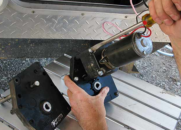
How to install electric landing gear on a semi-trailer?


Roton Intelligence Sets the Stage at Hannover Messe 2024


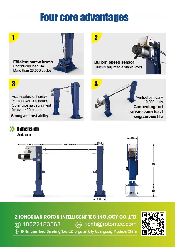
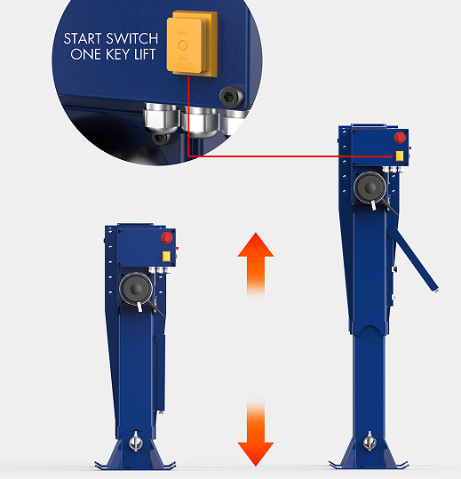
What is the Electric landing gear on a semi trailer?

Electric landing gear on a semi trailer is an automated system that replaces manual cranking for lifting and stabilizing the trailer.
Components and Functionality
Key Components of Electric Landing Gear
Electric landing gear systems integrate several critical components:
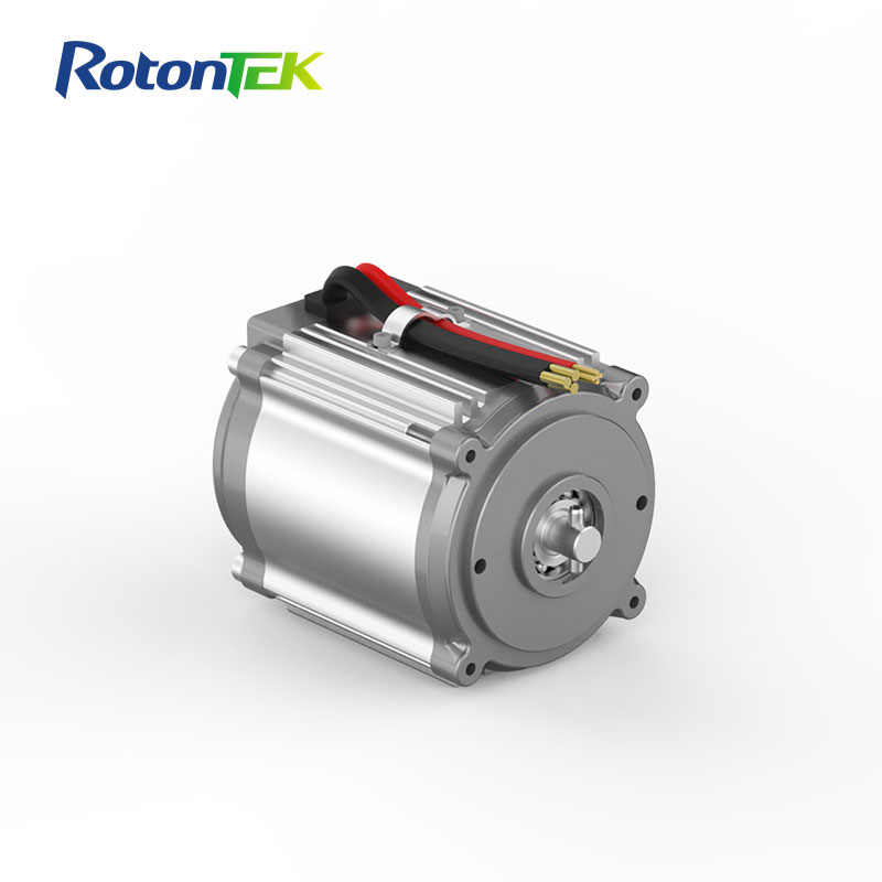
- Electric Motor: This is the heart of the system, typically with a power range of 1.5 to 3.0 kW, providing the necessary force for lifting.
- Transmission System: Includes gears and shafts, designed for optimal force transmission with minimal energy loss.
- Control Unit: A user-friendly interface, often equipped with wireless remote control, for effortless operation.
- Battery Pack: Supplies power, usually capable of multiple lift and lower cycles on a single charge.
Mechanism of Operation
The operation mechanism of electric landing gear includes:
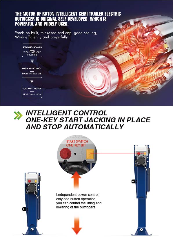
- Activation: Initiated by the control unit, which starts the electric motor.
- Lifting Process: The motor powers the transmission system, efficiently lifting or lowering the trailer.
- Safety Features: Integrated sensors and auto-stop functions enhance operational safety and prevent damage.
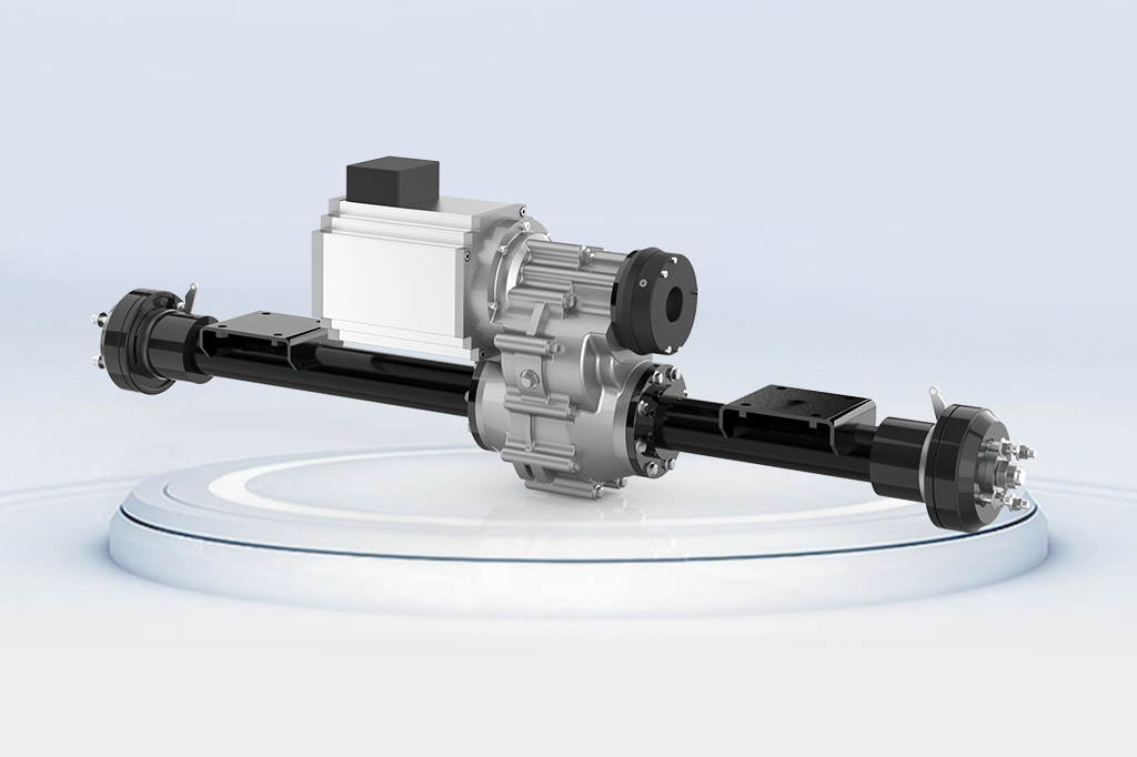
Comparison with Traditional Landing Gear
| Feature | Electric Landing Gear | Traditional Landing Gear |
|---|---|---|
| Operation Speed | Rapid, typically under 60 seconds for complete operation. | Slower, often taking several minutes. |
| Physical Effort | Minimal, operated with a button press. | Manual, requiring significant effort. |
| Maintenance | Mainly electrical components, less frequent maintenance. | More frequent due to mechanical wear. |
| Cost | Higher initial cost but savings in labor and efficiency over time. | Lower initial, higher long-term costs. |
| Weight | Slightly heavier due to additional components. | Lighter. |
| Lifespan | Longer, often exceeding 10 years, due to reduced mechanical strain. | Shorter due to manual operation. |
| Environmental Impact | Lower; no hydraulic fluids required. | Higher due to fluid usage. |
| User Safety | Enhanced with automated controls and safety features. | Higher risk of injury with manual use. |
Electric Landing Gear: Efficiency and Durability Electric landing gears, such as those from Rotontek, are designed for durability and efficiency. These systems not only save time but also reduce the physical strain on operators. Their integration into semi-trailers represents a significant step forward in terms of safety, cost-effectiveness, and environmental friendliness.
Installation and Maintenance of Electric Landing Gear on Semi Trailers
Installing Electric Landing Gear on Semi Trailers
The installation of electric landing gear on semi trailers is a critical process that demands precision. It involves selecting a gear system that aligns with the trailer’s weight capacity and dimensions. The installation includes secure mounting, ensuring the electric system is properly wired to the trailer’s power supply. Typically, these systems require a power output ranging from 1.5 to 3.0 kW. Post-installation, a comprehensive testing of the gear’s functionality and safety features is crucial.
Routine Maintenance and Care
Maintaining electric landing gear is key to its longevity and efficient operation. This involves regular inspections for wear or damage, particularly focusing on the motor and transmission system. Regular lubrication of moving parts is vital to minimize friction and wear. Battery maintenance is also crucial; it should be kept charged and stored correctly. Additionally, keeping the control unit’s software updated ensures the system operates at peak efficiency.
Troubleshooting Common Issues
Common issues with electric landing gear include motor malfunctions, which often relate to power supply problems or battery issues. Unusual noises during operation may indicate a problem with gears or shafts, necessitating inspection and lubrication. Slow operation can be a symptom of a depleted battery or a malfunction in the transmission system, requiring thorough testing and possible component replacement.
Key Points for Effective Management:
- Ensure compatibility of the landing gear with the trailer’s specifications during installation.
- Conduct routine maintenance, including inspections, lubrication, and battery care, to maintain efficiency and safety.
- Address common issues by checking the power supply, mechanical components, and maintaining regular upkeep.
Benefits and Applications of Electric Landing Gear
Advantages Over Manual Systems
Electric landing gear offers numerous benefits compared to manual systems:
- Reduced Physical Effort: Eliminates the manual cranking required by traditional systems, significantly reducing the physical strain on operators.
- Increased Safety: With automated controls, the risk of injuries associated with manual operation is greatly minimized.
- Time Efficiency: Electric systems can lift or lower a trailer in less than a minute, a task that takes several minutes manually.
- Consistent Performance: Unlike manual systems, which can vary in efficiency due to human effort, electric gear provides consistent lifting power.
Efficiency and Productivity Improvements
The introduction of electric landing gear in semi trailers has led to significant efficiency and productivity improvements:
- Quicker Turnaround Times: Speedy operation enables faster loading and unloading, enhancing overall workflow efficiency.
- Lower Maintenance Costs: Electric systems typically require less maintenance than manual gear, translating to cost savings and less downtime.
- Long-Term Durability: With fewer moving mechanical parts than manual systems, electric landing gear tends to have a longer lifespan, often exceeding 10 years.
Use Cases in Different Types of Trailers
Electric landing gear finds its application across various types of trailers, demonstrating its versatility:
- Flatbed Trailers: Enhances ease of loading/unloading heavy cargo.
- Refrigerated Trailers: Useful in temperature-sensitive cargo operations where time efficiency is critical.
- Tanker Trailers: Provides stability and safety, crucial for transporting liquids.
- Specialty Trailers: In trailers with unique requirements, electric gear can be tailored to meet specific operational needs.
Key Insights:
- Electric landing gear significantly reduces physical effort and enhances safety in trailer operations.
- It leads to better efficiency and productivity, with faster operations and lower maintenance requirements.
- The gear is adaptable to various trailer types, catering to a wide range of industry needs.

Technological Integration in Electric Landing Gear
Integration with Other Trailer Systems
Electric landing gear is increasingly becoming an integral part of the broader trailer system, offering seamless integration capabilities:
- Synchronized with Braking Systems: Integration with the trailer’s braking system allows for automated stability control during loading and unloading operations.
- Connectivity with Telematics Systems: Real-time data sharing with fleet management systems enhances operational efficiency and safety.
- Compatibility with Various Trailer Types: Designed to be adaptable across different trailer designs, from flatbeds to tankers.
Smart Technologies and Automation
The incorporation of smart technologies into electric landing gear systems is revolutionizing trailer operations:
- Remote Operation: Operators can control the landing gear via smartphones or remote devices, enhancing convenience and safety.
- Automated Positioning and Leveling: Advanced sensors and software enable precise control over the landing gear’s position and level, crucial for safe loading and unloading.
- Predictive Maintenance: Integration with diagnostic tools allows for predictive maintenance, reducing downtime and increasing the lifespan of the gear.
Future Trends in Electric Landing Gear Technology
The future of electric landing gear technology is poised for further advancements:
- Increased Energy Efficiency: Development of more energy-efficient motors and battery systems to reduce power consumption and enhance operational time.
- Solar-Powered Systems: Exploration of solar panels for auxiliary power supply, promoting sustainability and reducing reliance on traditional power sources.
- Integration with Autonomous Trailers: As autonomous driving technology advances, electric landing gear will play a crucial role in fully automated trailer operations.
Key Takeaways:
- Electric landing gear is becoming a central component in the modern semi-trailer ecosystem, offering enhanced integration with other systems.
- The use of smart technologies leads to improved operational control, safety, and predictive maintenance capabilities.
- Anticipated future trends include greater energy efficiency, solar power integration, and compatibility with autonomous trailers.
Safety and Regulatory Considerations for Electric Landing Gear
Safety Features of Electric Landing Gear
Electric landing gear is equipped with numerous safety features designed to protect operators and ensure the secure handling of trailers:
- Automatic Load Sensing: This system prevents over-extension or excessive force application, crucial for maintaining structural integrity.
- Emergency Stop Mechanism: In case of a malfunction or hazard, the emergency stop feature allows immediate cessation of all operations.
- Built-in Safety Locks: These locks engage automatically to prevent unintended retraction or deployment, enhancing stability during loading and unloading.
- Weather-Resistant Design: The gear is built to withstand extreme weather conditions, ensuring reliable operation in diverse environments.
Compliance with Transportation Regulations
Adherence to transportation regulations is paramount for electric landing gear:
- Certification Standards: Electric landing gear must meet specific industry standards, such as ISO or ASTM, to ensure safety and reliability.
- Regular Inspections: Mandatory inspections as per transportation authority guidelines help maintain compliance and operational safety.
- Documentation and Record-Keeping: Keeping accurate records of maintenance and inspections is essential for regulatory compliance.
Environmental Impact and Sustainability
Electric landing gear also plays a role in environmental sustainability:
- Reduced Carbon Footprint: By eliminating the need for hydraulic fluids and reducing the effort required for operation, electric landing gear contributes to lower emissions.
- Energy Efficiency: Advanced motor and battery technologies aim to optimize energy usage, reducing the overall environmental impact.
- Recyclability: Manufacturers are increasingly focusing on using recyclable materials and sustainable production methods.
Overall Impact:
- Electric landing gear enhances safety with features like automatic load sensing and emergency stops.
- Regulatory compliance is achieved through certification standards and regular inspections.
- Its role in environmental sustainability is marked by reduced emissions and energy efficiency.
Referensi
Electric landing gear motors generally have a power range between 1.5 to 3.0 kW, providing sufficient force for lifting trailers efficiently. While electric landing gear has a higher initial cost compared to manual systems, it offers long-term savings in labor and maintenance, making it cost-efficient over time. Key safety features include automatic load sensing to prevent over-extension, emergency stop mechanisms, built-in safety locks, and a weather-resistant design for reliable operation in diverse environments. Electric landing gear reduces carbon emissions by eliminating the need for hydraulic fluids and improves energy efficiency with advanced motor and battery technologies. Electric landing gear often has a longer lifespan, frequently exceeding 10 years, due to reduced mechanical strain compared to manual systems. It can synchronize with braking systems, connect with telematics for real-time data sharing, and is compatible with various trailer types, enhancing overall operational efficiency. Future trends include more energy-efficient motors, solar-powered systems for auxiliary power, and integration with autonomous trailers. In various trailers like flatbeds, refrigerated, and tanker trailers, electric landing gear enhances loading efficiency, provides stability, and improves safety in operations.
What power range is typical for electric landing gear motors?
How does the cost of electric landing gear compare to manual systems?
What are the main safety features of electric landing gear?
How does electric landing gear contribute to environmental sustainability?
What is the typical lifespan of electric landing gear?
How does electric landing gear integrate with other trailer systems?
What advancements are expected in electric landing gear technology?
What are the benefits of electric landing gear in different types of trailers?
The Growing Impact of Integrated Electric Drive Technology

Integrated electric drives are revolutionizing industries by enhancing efficiency, reliability, and reducing costs, extending beyond automotive applications.
Introduction to Integrated Electric Drive Systems
Emergence in the Technological Landscape
The rise of integrated electric drive systems marks a significant milestone in the evolution of technology. These systems, characterized by their high efficiency and low operational costs, are reshaping the landscape of electric power usage. Electric drive systems, with a power range typically between 50 kW to 500 kW, offer an unprecedented balance of efficiency and performance. The integration of these systems has been driven by the need for more compact designs, leading to reduced space requirements and enhanced energy efficiency.
Integrated electric drives, made from advanced materials, showcase remarkable quality and durability, extending their lifespan significantly. The materials used, such as high-grade copper and rare-earth magnets, contribute to their robust construction and high performance. These drives operate at impressive speeds, often exceeding 10,000 RPM, ensuring swift and responsive performance in various applications.
Role in Automotive Industry Advancements
In the automotive industry, integrated electric drive systems have become pivotal. They are central to the development of electric and hybrid vehicles, offering a combination of low cost, high efficiency, and compact size. For instance, in modern electric cars, these systems have enabled manufacturers to reduce production costs by up to 30% while enhancing vehicle performance. The integration of the motor, gear reducer, and controller into a single unit has streamlined manufacturing processes, resulting in significant savings in both time and resources.
These systems have also contributed to advancements in vehicle speed and range. With integrated electric drives, vehicles can achieve top speeds of up to 250 km/h and offer an extended range, some models reaching up to 500 km on a single charge. This advancement is not just in performance but also in reducing the overall weight of the vehicle, further enhancing efficiency.
Integrated electric drive systems are revolutionizing industries with their cost-effectiveness, high quality, and superior performance. Their impact on the automotive industry is particularly noteworthy, paving the way for more sustainable and efficient transportation solutions.

User-Friendly Design of Integrated Electric Drives
Simplification of User Experience
The design of integrated electric drives focuses heavily on user experience, prioritizing simplicity and ease of use. These systems feature intuitive interfaces, making them accessible even to those with limited technical knowledge. The goal is to reduce the complexity typically associated with electric drive systems, thereby making them more appealing to a broader audience.
For instance, the control panels on these drives often include simple, touch-screen interfaces with clear, easy-to-understand instructions. This approach eliminates the need for extensive training or technical background to operate the drives, which is especially beneficial in sectors where quick adoption of technology is crucial.
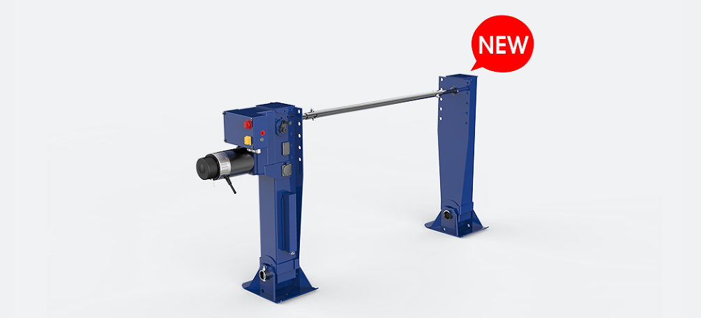
Integration of Motor, Gear Reducer, and Controller
The core innovation in integrated electric drives lies in the seamless combination of the motor, gear reducer, and controller. This integration results in a compact design, often reducing the overall size by up to 40% compared to traditional systems.
- Motor: The electric motor in these systems is designed for high efficiency, often exceeding 90%. This efficiency translates into lower energy consumption and reduced operational costs.
- Gear Reducer: The gear reducer complements the motor by providing optimal torque. It’s engineered for minimal energy loss, contributing to the overall efficiency of the system.
- Controller: The integrated controller is the brain of the system, precisely managing power distribution and performance parameters. Advanced models can adapt to different operating conditions, enhancing the longevity and reliability of the drive.
These components, when integrated, offer significant cost savings in both manufacturing and maintenance. By reducing the number of separate parts, the system minimizes potential points of failure, thus enhancing its durability and reducing maintenance costs.
The user-friendly design of integrated electric drives is a significant advancement, making powerful technology accessible and easy to use. Their compact size, combined with high efficiency and reduced cost, makes them an ideal choice for a variety of applications.
Enhanced Reliability and Electromagnetic Compatibility
Improving System Robustness
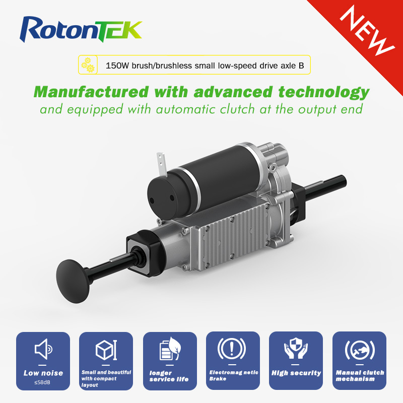
Integrated electric drive systems, such as those exemplified by products like the “small low-speed drive axle,” have significantly enhanced system robustness, primarily due to their advanced design and superior material quality. Key components are engineered to withstand high operational stress, often operating reliably in a power range from 50 kW to 500 kW. The robustness of these systems is not just about handling high power; it also involves long-term durability. Many of these systems have a life expectancy that exceeds 20 years, reducing the frequency of replacements and repairs.
Materials like high-grade steel and advanced polymers in the construction of these drives contribute to their resilience against wear and tear. Moreover, manufacturers select these materials for their robustness in facing harsh environmental conditions, ensuring the drives function effectively in extreme climates with temperatures spanning from -40°C to 85°C.
Benefits of Streamlined Design
The streamlined design of integrated electric drives offers numerous benefits, key among them being improved electromagnetic compatibility (EMC). By integrating the motor, gear reducer, and controller into a single unit, these systems minimize electromagnetic interference, crucial in environments with multiple electronic devices.
This integration also leads to reduced manufacturing costs, as the production process becomes more streamlined, cutting down on material and labor expenses. The compact design further reduces shipping and storage costs, a significant advantage for companies looking to optimize their budget.
Furthermore, the streamlined design contributes to energy efficiency. Integrated drives often exhibit an efficiency rate of over 90%, meaning a greater portion of the electrical energy is effectively converted into mechanical energy. This efficiency, evident in the small low-speed drive axle, not only reduces energy costs but also minimizes heat generation, prolonging the life of the system and reducing cooling requirements.
The enhanced reliability and electromagnetic compatibility of integrated electric drives represent a substantial leap forward in drive technology. These systems offer a combination of durability, efficiency, and cost-effectiveness, making them a preferred choice in various industrial applications.
Cost Reduction Through Integration
Traditional vs. Integrated Manufacturing Processes
In traditional manufacturing processes, components like motors, gear reducers, and controllers were produced separately, each requiring individual assembly lines, storage facilities, and transportation logistics. This approach, while standard, incurred significant costs in terms of materials, labor, and operational overhead. Typically, the production of each component separately could increase the overall manufacturing cost by up to 20-30%.
In contrast, integrated electric drive systems streamline this process by combining these key components into a single unit. This integration significantly reduces the number of assembly steps and simplifies the supply chain, leading to a marked decrease in production costs. Material usage is optimized, cutting down waste and reducing expenses. Moreover, the need for separate storage and transportation for each component is eliminated, further lowering logistical costs.
Economic Implications for Industries
The economic implications of adopting integrated electric drives are profound across various industries. By reducing production and operational costs, companies can offer more competitive pricing while maintaining or improving profit margins. In the automotive industry, for instance, integrating electric drive systems has led to cost reductions of approximately 30% per vehicle.
Moreover, the high efficiency and lower energy consumption of these integrated systems translate into long-term cost savings for end-users. Efficiency rates of these systems often surpass 90%, leading to substantially lower operational costs in energy usage when compared to traditional systems. This efficiency not only reduces the electricity bills but also minimizes the environmental impact, potentially leading to lower carbon taxes and environmental compliance costs.
Furthermore, the increased reliability and longer lifespan of integrated systems reduce maintenance and replacement costs. A typical integrated electric drive can have a lifespan extending over 20 years, reducing the frequency and cost of replacements.
The shift to integrated electric drive systems represents a significant cost-saving opportunity for industries, enabling them to leverage technological advancements for economic benefits.
Broader Applications Beyond Automotive Sector
Potential in Off-Road Vehicles
Integrated electric drive systems are finding increasing applications in off-road vehicles, such as ATVs, construction equipment, and military vehicles. These environments demand high power and robustness, where electric drives excel. Systems used in these vehicles typically operate in the 100 kW to 600 kW power range, providing substantial torque and speed required for challenging terrains.
One significant advantage is the reduction in maintenance costs, as integrated systems have fewer moving parts and a sealed design, protecting against dust and moisture. This durability is crucial in off-road conditions, where vehicles face harsh environments. The integration leads to compact and lightweight designs, improving vehicle maneuverability and reducing energy consumption.
Advancements in Agriculture Vehicle Technology
In the agriculture sector, integrated electric drives are revolutionizing the design and efficiency of tractors, harvesters, and other farming equipment. These drives offer improved efficiency, with energy savings up to 30% compared to conventional diesel-powered vehicles. The precision control provided by integrated electric drives leads to better crop yield and reduced waste, a crucial factor in modern sustainable farming practices.
The use of electric drives in agriculture machinery also contributes to a reduction in noise and air pollution, enhancing the working environment for farmers. Moreover, the lower operational costs associated with electric drives make them a cost-effective solution in the long run.
Integration in Architectural Machine Industry
The architectural machine industry, encompassing equipment used in building and construction, is also benefiting from the integration of electric drive systems. These systems offer enhanced precision and control in machines like cranes, lifts, and drilling equipment, which is pivotal in construction tasks.
The compact size of integrated drives allows for more flexible design of machinery, making them suitable for use in confined urban construction sites. Additionally, the higher efficiency and lower energy consumption of these drives lead to reduced operational costs, a significant advantage given the tight budgets and high energy demands typical in construction projects.
The expansion of integrated electric drive systems into off-road vehicles, agriculture, and architectural machinery signifies a major shift towards more efficient, durable, and cost-effective machinery across various industries.
What are the advantages of a transaxle?

The advantages of a transaxle include improved weight distribution, enhanced vehicle performance, design and packaging efficiency, drivetrain flexibility, improved fuel efficiency, and increased durability and maintenance benefits.
Improved Weight Distribution
Balancing Vehicle Weight
Transaxles, by design, combine the transmission, differential, and axle assembly into one integrated unit. This layout often shifts the weight distribution toward the rear of the vehicle, particularly in rear-wheel and all-wheel drive configurations. This rearward weight bias enhances traction, especially during acceleration. In sports cars where performance is crucial, this setup contributes significantly to a balanced weight distribution, ensuring that the vehicle remains stable at high speeds and while cornering.
A notable example is the Porsche 911, renowned for its rear-engine layout combined with a transaxle, which optimizes its weight distribution and driving dynamics. The 911 models typically show a rear weight distribution of around 39% front and 61% rear, which is quite distinct from the conventional 50:50 or front-heavy layouts seen in many sports cars.
Effects on Handling and Stability
A well-distributed weight balance is essential for effective handling and stability. Transaxles contribute by equalizing the weight across the vehicle’s chassis. This equilibrium reduces the tendency for either understeer or oversteer, common issues in front-heavy or rear-heavy vehicles, respectively. For instance, a balanced car like the Alfa Romeo Giulia, with a near perfect 50:50 weight distribution, provides precise steering and stable handling characteristics, crucial for safety and performance.
Comparative Analysis with Front or Rear-Only Drive Systems
When comparing transaxle-equipped vehicles to those with front or rear-only drive systems, the distinction in handling and performance becomes apparent. Front-wheel drive (FWD) vehicles, where the engine and transmission are located in the front, often deal with higher front-end weight leading to understeer. In contrast, traditional rear-wheel drive (RWD) vehicles might struggle with oversteer due to a heavier rear end.
The weight distribution in a typical FWD vehicle like the Honda Civic can be around 60% on the front axle and 40% on the rear, leading to a front-heavy bias. On the other hand, a classic RWD car like the Ford Mustang might exhibit approximately 55% rear and 45% front distribution.
Comparatively, vehicles with transaxles can achieve a more neutral weight balance. This balance not only affects handling but also contributes to even tire wear, potentially reducing maintenance costs over time. The cost savings from tire wear, however, need to be balanced against the typically higher initial cost of transaxle systems due to their complexity and advanced engineering. Despite the higher upfront cost, the long-term benefits in terms of handling, stability, and reduced tire wear can present a compelling value proposition over time.

Enhanced Vehicle Performance
Impact on Acceleration and Speed
Transaxles significantly influence a vehicle’s acceleration and top speed. By optimizing weight distribution and improving traction, cars with transaxles typically exhibit quicker off-the-line acceleration. The rearward shift in weight during acceleration pushes the rear tires down, enhancing their grip. This effect allows for more effective power transfer from the engine to the wheels, crucial for rapid acceleration.
For example, the Ferrari 488 GTB, equipped with a transaxle layout, boasts a 0 to 100 km/h (62 mph) acceleration time of just 3 seconds. This performance is not only due to the engine’s high power output of about 661 horsepower but also because of the efficient power transfer enabled by the transaxle.
Contribution to Torque Distribution
Transaxles play a critical role in torque distribution, especially in vehicles featuring all-wheel-drive (AWD) systems. They ensure that the engine’s torque efficiently reaches the wheels with the most grip. This efficient distribution of torque not only enhances the vehicle’s acceleration but also improves handling and stability in various driving conditions.
In the context of AWD systems, such as those found in the Audi Quattro lineup, the transaxle works in concert with the car’s drivetrain to variably distribute power between the front and rear wheels. This feature is particularly beneficial in slippery or off-road conditions, where it can redirect torque to the wheels with the most traction, thereby enhancing safety and performance.
Transaxle Systems in Sports and Racing Cars
Transaxles are crucial in sports and racing cars for better vehicle dynamics. They help achieve a low center of gravity and ideal weight distribution, essential for stability and cornering at high speeds.
In racing like Formula 1, transaxles combined with aerodynamics enable cars to reach up to 5g in cornering lateral forces, showcasing their importance in enhancing vehicle dynamics. This technology is vital for top speed, handling, and efficiency in races.
High-performance sports cars, like those from Ferrari and Porsche, use transaxles for improved driving experience and performance, despite the higher cost and complexity. These cars show that the benefits of better power delivery, balance, and handling justify the extra expense and engineering in sports car design.
Design and Packaging Efficiency
Space Saving in Vehicle Design
Transaxles offer a unique advantage in terms of vehicle design and packaging. By combining the gearbox and axle into one unit, they reduce the need for separate components and can lead to more compact vehicle designs. This integration allows designers to maximize cabin space or to create more streamlined and aerodynamic vehicle profiles, which are essential in modern vehicle design for both aesthetic and performance reasons.
For example, the Mazda MX-5 Miata, a compact roadster, utilizes a transaxle layout to maximize its interior space while maintaining a small, lightweight design. This arrangement contributes to the Miata’s low weight of just around 1,000 kg, which in turn enhances its agility and fuel efficiency.
Integration with Hybrid and Electric Powertrains
Transaxles are particularly beneficial in the design and efficiency of hybrid and electric vehicles (EVs). In these vehicles, the transaxle can integrate not just the transmission and axle, but also the electric motor and power electronics into a single compact unit. This efficiency in space utilization is critical in EVs and hybrids, where battery packaging and weight distribution are key design considerations.
The Tesla Model S, for example, uses an advanced electric powertrain integrated into a transaxle, which allows for a spacious interior and a large battery pack situated along the vehicle’s floor. This design lowers the vehicle’s center of gravity, enhancing stability and handling while providing ample space for passengers and luggage.
Case Studies: Compact and Mid-Engine Cars
Compact and mid-engine cars greatly benefit from transaxle designs. In mid-engine cars, positioning the transaxle behind the driver optimizes weight distribution and handling. This setup is common in many high-performance sports cars where balance, handling, and weight distribution are crucial to the car’s overall performance.
The Porsche 718 Boxster, with its mid-engine layout, is a prime example. The car’s transaxle arrangement allows for near-perfect weight distribution, contributing to its renowned handling characteristics. Another example is the Ferrari 458, which utilizes a rear mid-engine, rear-wheel-drive layout where the transaxle plays a vital role in achieving its exceptional handling and responsiveness.
In both cases, the transaxle’s ability to improve vehicle balance and handling is a key factor in the design and performance of these cars. It demonstrates how car manufacturers leverage transaxle systems to enhance the driving experience in both everyday compact cars and high-performance sports cars. This approach underlines the importance of a thoughtful design that incorporates efficient use of space, optimal weight distribution, and integration of advanced drivetrains to meet the evolving demands and expectations of modern drivers.

Drivetrain Flexibility
Compatibility with Different Engine Layouts
Transaxle systems offer exceptional flexibility in terms of compatibility with various engine layouts. Whether it’s a front-engine, mid-engine, or rear-engine layout, transaxles can efficiently transfer power to the drive wheels. This versatility allows automobile manufacturers to experiment with different layouts to achieve specific performance, handling, and space utilization goals.
In front-engine cars, transaxles can help balance the weight by placing the transmission at the rear, as seen in the Chevrolet Corvette. The Corvette, particularly in its latest iterations, uses a front-engine, rear-transaxle layout to achieve a more balanced weight distribution, enhancing its performance and handling.
Front-Wheel Drive, Rear-Wheel Drive, and All-Wheel Drive Configurations
Transaxles are adaptable to various drivetrain configurations – Front-Wheel Drive (FWD), Rear-Wheel Drive (RWD), and All-Wheel Drive (AWD).
- FWD Systems: In FWD vehicles, the transaxle combines the functionality of the transmission, differential, and drive axle into one integrated unit mounted in the front of the vehicle. This compact setup, used in cars like the Honda Accord, maximizes passenger space and is cost-effective to manufacture.
- RWD Systems: In RWD applications, the transaxle is typically placed at the rear of the vehicle, balancing the weight more evenly between the front and rear. This configuration, found in performance cars like the Porsche 911, optimizes traction and handling.
- AWD Systems: AWD vehicles, such as the Audi Quattro, use transaxles that distribute power to both the front and rear wheels. This setup can enhance grip and stability, especially in slippery conditions.
Examples in Various Vehicle Types (Sedans, SUVs, Sports Cars)
Transaxle systems find applications across a diverse range of vehicle types, underlining their versatility.
- Sedans: Many luxury sedans, like the Mercedes-Benz E-Class, employ transaxles to achieve a quiet and comfortable ride, coupled with efficient power delivery.
- SUVs: In SUVs, transaxles can provide a balance between on-road comfort and off-road capability. The Jeep Grand Cherokee, for instance, uses a sophisticated AWD system, often coupled with a transaxle to optimize performance across different terrains.
- Sports Cars: For sports cars, such as the Ferrari 488, the transaxle layout is critical for achieving high-speed stability and agile handling. By balancing the weight distribution and lowering the center of gravity, transaxles help in extracting maximum performance from these vehicles.
In each vehicle type, the transaxle plays a crucial role in defining the vehicle’s character and capabilities. From enhancing passenger space in sedans to improving off-road readiness in SUVs, and boosting performance in sports cars, the flexibility of transaxles makes them an integral part of modern automotive design and engineering.

Improved Fuel Efficiency
The Role of Transaxles in Reducing Vehicle Weight
Transaxles contribute significantly to reducing overall vehicle weight, which directly influences fuel efficiency. By integrating components of the transmission and driveline into a single unit, transaxles eliminate the need for some heavy drivetrain parts found in traditional setups. This weight saving, although varying across different models and designs, can be substantial. For instance, sports cars like the Porsche 911 leverage this weight reduction to enhance both performance and fuel economy.
Impact on Aerodynamics and Energy Consumption
A transaxle’s compact design not only saves weight but also aids in creating more aerodynamic vehicle shapes. An aerodynamic vehicle reduces air resistance while moving, which subsequently decreases energy consumption. For example, electric vehicles (EVs) such as the Tesla Model 3 utilize a transaxle layout to achieve a lower profile, which enhances their aerodynamic efficiency and extends the range.
Improved aerodynamics can lead to notable reductions in fuel or energy consumption. In terms of specific numbers, a vehicle’s fuel efficiency can improve by about 0.1% for every 1% reduction in aerodynamic drag. This relationship highlights the importance of transaxles in the design of both fuel-efficient combustion vehicles and long-range EVs.
Contribution to Sustainable Automotive Technologies
Transaxles play a key role in sustainable vehicle development. They improve efficiency in hybrid and electric vehicle designs.
In the Toyota Prius, the transaxle balances power between the engine, motor, and wheels, boosting fuel efficiency and lowering emissions. For electric vehicles, transaxles enhance power transfer from motor to wheels, leading to better mileage and less energy use.
Their use in these vehicles underlines their importance in moving towards more sustainable and efficient automotive technologies. As transaxle designs evolve, their impact on fuel efficiency and sustainability in cars is set to increase.

Durability and Maintenance
Comparing Lifespan and Reliability with Conventional Transmission Systems
Transaxle systems offer an advantage in both lifespan and reliability over traditional transmission systems. The key reason for this stems from the integrated structure of the transaxle, which combines the transmission and differential into one compact unit. This integration minimizes the mechanical complexity and number of potential failure points, leading to a longer and more reliable operational life.
For instance, conventional transmission systems typically require maintenance or replacements more frequently than transaxles. The average lifespan of a transaxle, with proper maintenance, often surpasses that of separate transmission and differential systems. Vehicles with transaxle systems can efficiently run upwards of 200,000 miles or more without requiring major repairs, a clear testament to their robustness and endurance.
Maintenance Requirements and Cost Effectiveness
Transaxle systems generally demand less maintenance, thereby offering cost savings over time. These systems eliminate the need for some of the separate components required in traditional drivetrains, reducing the likelihood of costly repairs and the frequency of maintenance.
The lower maintenance requirement translates to significant cost savings. For instance, transaxle fluid change intervals tend to be longer compared to separate transmission and differential fluid changes. The overall maintenance cost can therefore be lower with transaxle systems, with savings becoming particularly noticeable over the long term.
User Experiences and Case Studies
Rotontek Brand Recommendation
Rotontek brand transaxles stand out in user experiences and case studies for their exceptional durability and low maintenance needs. Users often cite Rotontek’s innovative design and quality manufacturing as key factors contributing to the prolonged lifespan and reliability of their vehicles’ drivetrain.
Case studies reveal that Rotontek transaxles need less maintenance and last longer. They reduce the total cost of owning a car, benefiting both individuals and fleet managers. Rotontek transaxles are durable, efficient, and cost-effective, making them a top choice for a reliable drivetrain.
Many users praise Rotontek for enhancing their vehicle’s life and lowering maintenance costs. Rotontek’s advanced technology and quality materials result in durable, high-performing, and valuable transaxles.
Referensi
- Transaxle – Wikipedia
- Automatic Transmission – Wikipedia
- Manual Transmission – Wikipedia
- Differential (mechanical device) – Wikipedia
- Drivetrain – Wikipedia
- Vehicle Dynamics – Wikipedia
How does a transaxle improve vehicle handling?
By balancing the vehicle’s weight more evenly between the front and rear, a transaxle improves handling and stability, offering better cornering and braking performance.
Can a transaxle impact a vehicle's acceleration?
Yes, transaxles contribute to more efficient torque distribution, often resulting in quicker acceleration and improved performance, particularly in rear-wheel and all-wheel-drive vehicles.
What are the packaging benefits of a transaxle in vehicle design?
Transaxles save space by combining the transmission and differential into one unit, allowing for more compact vehicle designs, especially in hybrid and electric cars where space is crucial for battery placement.
Does a transaxle system offer flexibility in drivetrain configurations?
Yes, transaxles are compatible with various drivetrain layouts including front-wheel drive, rear-wheel drive, and all-wheel drive, making them versatile for use in different vehicle types from sedans to sports cars.
Are there fuel efficiency gains with transaxle systems?
Transaxle systems help reduce overall vehicle weight and can improve aerodynamics, contributing to lower energy consumption and better fuel efficiency.
What's the difference in maintenance costs between transaxles and conventional transmissions?
Transaxle systems generally require less frequent maintenance than separate transmission and differential systems, leading to lower long-term maintenance costs.
How does the durability of a transaxle compare to traditional transmissions?
Transaxles often have a longer lifespan due to their integrated design and fewer moving parts, resulting in increased reliability and lower chances of failure.
What is the average lifespan of a vehicle with a transaxle?
With proper maintenance, vehicles equipped with transaxles can efficiently run for over 200,000 miles, highlighting their extended lifespan compared to vehicles with traditional transmission systems.