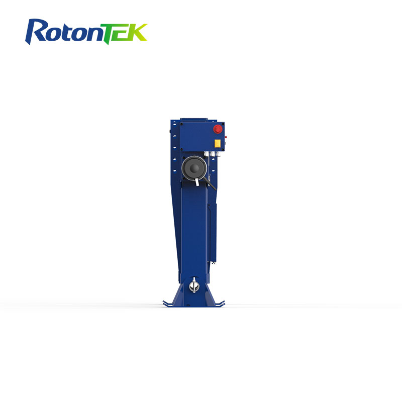
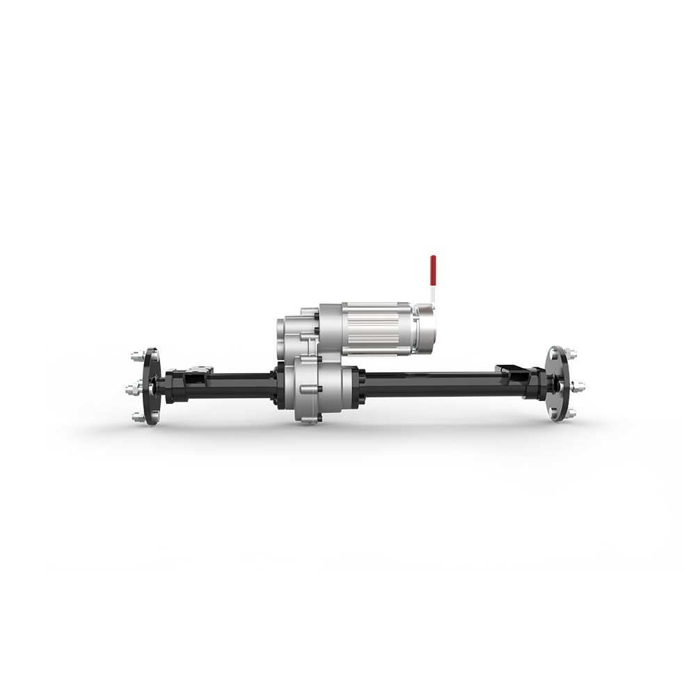
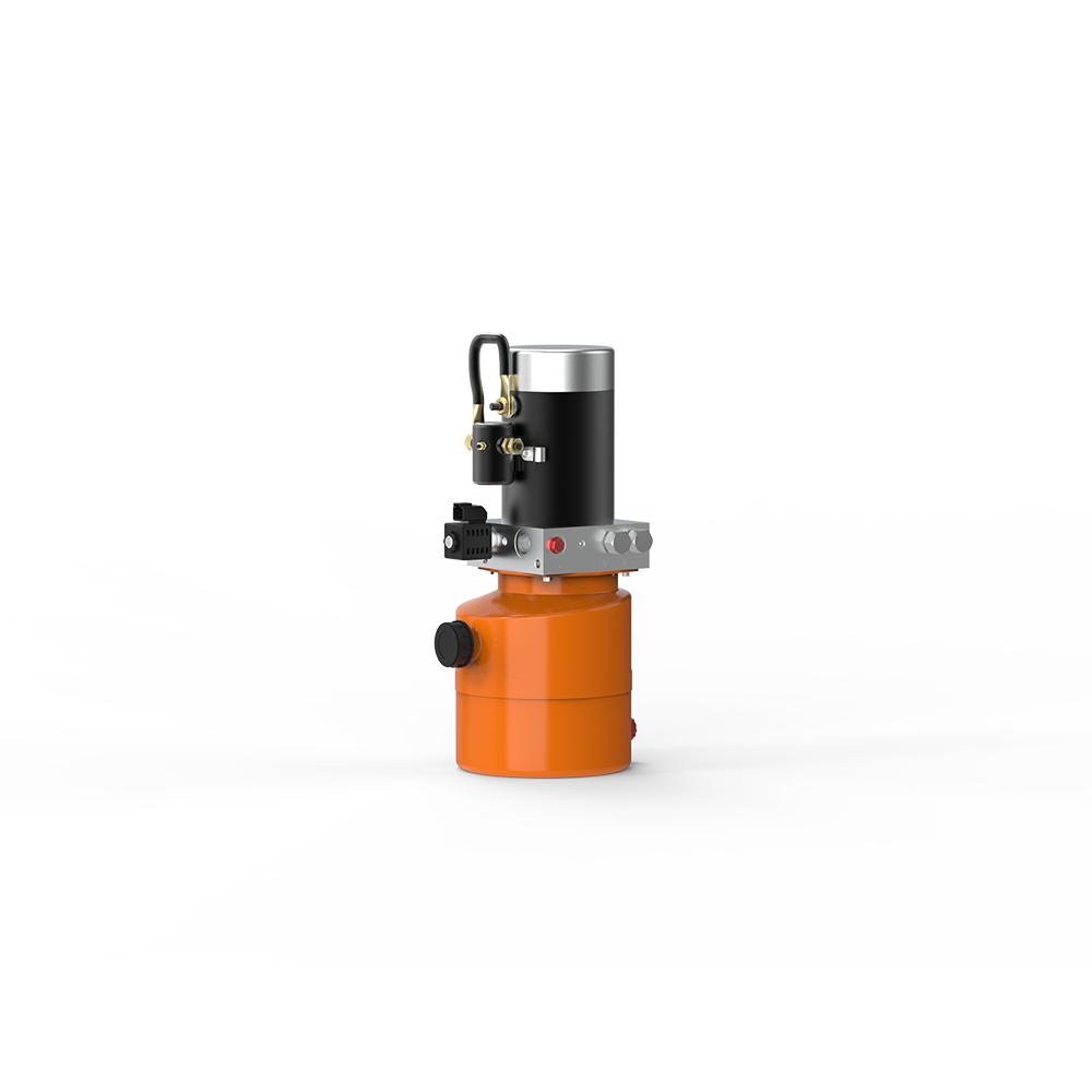
What are the components of a electric landing gear

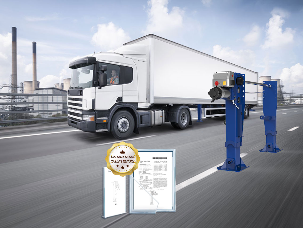
What is the Electric landing gear on a semi trailer

The core of the electric landing gear contains an eight-layer sensor array (detecting 0.01g vibration/0.1MPa pressure), a titanium alloy support structure (resisting 200MPa pressure), a planetary roller screw (contact area increased by 5 times) and a 32-bit MCU control system (2000 operations/second). The power module switches to the backup power supply in 3 milliseconds, and the buffer unloads the force by nitrogen pressure (the viscosity of the hydraulic oil in the first 70% of the stroke is ≤45cSt).

Drive motor

The motor of the electric outrigger of the truck is much more powerful than that of the RV. This thing has to withstand the brute force of a 30-ton heavy truck unloading its cargo with its body tilted, and it has to be as steady as an old dog in the mud. Now the mainstream is divided into two schools: brushed motors are cheap and durable, and brushless motors are precise and power-saving, just like the difference between manual and automatic transmissions.

The carbon brush of the brushed motor is a delicate bag. The mud and water mixture on the construction site can directly cut the life of the carbon brush in half. Last year, a fleet in Shandong replaced the inferior carbon brushes, and as a result, 8 of the 12 outriggers were burned during unloading. Experienced drivers all know that you have to use a motor with IP67 protection level, and the waterproof rubber ring should be as tight as a condom – don’t laugh, someone really did a comparative experiment with Durex.

The reduction box is the key to the burst of power. Although the efficiency of the worm gear structure is only 60%, the self-locking feature can save lives at critical moments. There is a counterintuitive design: after the outrigger is fully extended, the motor will rotate half a circle more, which is to offset the gap by pre-tightening the gear deformation. It’s like the last “click” sound when twisting the bottle cap. Without this design, the outrigger will shake like dancing.
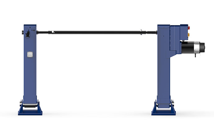
Semi-trailer intelligent electric landing gear

Control system

The control system of the RV electric outrigger is much more pretentious than that of the truck. You have to take care of the millimeter-level leveling of the four outriggers at the same time, and you have to be careful of the slope of the camping site. Nowadays, high-end RVs all use dual control systems: the touch screen panel is used for show, and the physical buttons are kept for life. Last year, a popular RV changed the buttons to full touch control. As a result, the operation failed when wearing gloves in winter, and the owner almost flipped over on the snow slope.

The pressure sensor here plays permutations and combinations. The 16 sensors on the four legs will play “elimination” – automatically find the three most stable fulcrums, and the leg that is suspended is used for fine-tuning. This trick is learned from the tripod, but with a fool-proof design: if the ground is uneven, the system will reselect points like a hopscotch game.

The anti-overload mechanism is the real IQ tax disaster area. Don’t really push the 5-ton outriggers to 5 tons. Leaving 20% margin is an industry unwritten rule. A ruthless person found in actual testing that the protection mechanism of a certain brand of outriggers was activated at 4.8 tons, and it can actually carry another 1 ton – this is like an airbag, it is better to trigger it by mistake than to have an accident. Just like the overload protection of CNC machine tools, the set value is always 15% ahead of the nominal value.

Power module

The power heart of the electric landing gear is a schizophrenic. It must have continuous output like a power bank, but also have the awareness of explosion-proof devices. The mainstream now is the lithium battery + supercapacitor combination package, just like the off-road vehicle is equipped with double fuel tanks – lithium batteries are responsible for long-term flow, and capacitors are specialized in treating instantaneous large currents.

The battery management system is deeper than the ICU of a tertiary hospital. There are 48 temperature probes hidden in the 16-series and 24-parallel battery pack, which is denser than the thermometers in a hot pot restaurant. Last year, a copycat manufacturer cut corners and cut the number of probes in half, and as a result, the battery set off fireworks directly in the heat wave of Dubai Airport. The serious solution must use active balancing technology, just like equipping each battery unit with a private nutritionist.

Emergency power supply is the real black technology. After the main power supply is off, the supercapacitor can take over the power supply within 3 milliseconds-this speed is enough for you to blink one-tenth of your eyes. What’s even more amazing is the self-destruct fuse, which will melt into two pieces when it encounters a short circuit, just like a spy capsule.

Lifting mechanism

This mechanical system plays with the philosophy of combining rigidity and flexibility. The screw drive should be as precise as a Swiss Army knife, and the buffer device should learn to unload force like Tai Chi. Now high-end products all use planetary roller screws. Don’t be fooled by the mysterious name, it is actually turning the toothpick of the traditional screw into a mace – the contact area increases by 5 times, and the life span is directly doubled.

The self-locking mechanism is the life-saving trick. The electromagnetic brake must bite like a trap at the moment of power failure, and a delay of more than 10 milliseconds can cause a disaster. There is a counter-intuitive design: a greater driving force is required when descending, which is to prevent gravity acceleration from causing trouble. It’s the same as stepping on the brake when going down a steep slope, except that the motor is desperately rotating in the opposite direction.

Overload protection plays a psychological game. The nominal 10-ton landing gear can actually carry 15 tons, but the protection program will be activated if it exceeds 12 tons – this 20% margin is not due to poor technology, but a regret medicine for reckless people. Just like the feed force limit of CNC machine tools, it is obviously able to be tough, but it pretends to be weak. The ground staff of a certain airline company once tested a container as a counterweight, but after the protection was triggered, they thought the equipment was faulty, which made a big joke.

The voltage tolerance setting of the electric landing gear is comparable to walking on a tightrope. Lowering the threshold can protect the circuit but is easy to trigger by mistake, and raising it may burn components. Actual combat data shows that in the high salt fog environment in the coastal area, the voltage fluctuation threshold should be relaxed by 8%, and the thickness of the gold plating layer of the connector should be increased.

Sensor

This pile of electronic probes is the real “drama queen”. It is necessary to play the role of an honest man of the weighing sensor and take into account the gymnast attributes of the tilt sensor. Nowadays, high-end cargo planes are equipped with an eight-layer sensor array: 3 pressures + 2 angles + 1 vibration + 2 temperatures, which is three more than the five senses of the human body.

The vibration sensor plays a spy game. Use MEMS accelerometers to capture tiny vibrations of 0.01g. This sensitivity can detect the movement of the flight attendant pushing the food cart in the cabin. Last year, a cargo plane landed and the system alarmed. After disassembling it, it was found that two ball bearings inside the landing gear were broken – the vibration spectrum is more accurate than B-ultrasound.

Temperature compensation is the real black technology. Stainless steel will shorten by 0.2mm compared to normal temperature at minus 40℃, and the sensor must be able to do math problems by itself. Just like the thermal deformation compensation of five-axis machine tools, the landing gear sensor has a built-in material expansion coefficient database. The accident of the Antarctic expedition team was caused by a certain copycat sensor that misjudged the resistance change caused by low temperature as abnormal force.

Support structure

This pile of metal skeletons is playing a balancing act of “wanting both”. It has to be harder than Wolverine’s adamantium, but as soft as a cat’s paw. 7075-T6 aluminum alloy is the basic model, but the real tough ones use titanium alloy + carbon fiber woven layer – this configuration is comparable to the chassis of an F1 car, but the price can buy three BMW 7 Series.

The buffer is the magician of mechanics. The oil-gas mixed buffer must accurately control the CP value of nitrogen pressure and hydraulic oil viscosity, just like mixing a cocktail, you have to pay attention to the proportion. The unique skill of Boeing 787 is the two-stage buffer: the first 70% of the stroke is gentle like water, and the last 30% is suddenly hard-core, just like the experience of eating popping candy.

The joint connection is ten times more complicated than the human knee. The self-lubricating bearing must withstand a pressure of 200MPa, and it must also prevent sandstorms from playing Infernal Affairs. The most damaging design is the anti-misinstallation buckle – different diameter pins have exclusive torque codes. Want to install violently? No way! I learned this trick from the CNC tool handle. Back then, a ground crew used a sledgehammer to install the wrong part. Now, the buckle is more sophisticated than a bank vault lock.

How does an electric landing gear work

Rotontek Electric landing gear

The electric outrigger is driven by a DC motor. At low temperatures, the 2A preheating current ensures that it starts at -35℃. The pressure sensor detects that the hardness difference between cement and mud is 4 times. The speed difference of the four motors is ≤5% and they stretch synchronously. When encountering obstacles, the 5Hz vibration mode is activated. The vibration sensor warns of bearing failure 200 times in advance.

Signal reception

Last year, a refrigerated truck of a logistics company broke down in Heilongjiang at minus 25 degrees. The driver pressed the outrigger button three times but it didn’t respond. Later, it was found that the remote control battery had insufficient voltage at low temperatures. The signal reception of the electric outrigger of the truck is like an experienced driver stepping on the clutch, which requires the coordination of force and timing.

When the driver presses the control button, the signal must pass three levels before it can take effect. First, it must pass the heartbeat detection of the on-board CAN bus. This mechanism is exactly the same as the anti-mistouch design of the truck ECU. If the signal lasts less than 0.3 seconds, it will be filtered out directly. Then it must pass the voltage fluctuation test, especially the circuit interference problem often encountered by modified vehicles. Last year, there was a case where the wiring harness was improperly routed during the modification of the car audio, causing the outrigger signal to be swallowed by the radio electromagnetic wave.

The most terrible thing is signal conflict processing. For example, a common scenario in RVs: on one side, the outriggers are deployed with the remote control, and on the other side, the onboard computer automatic leveling system is also sending instructions. At this time, the arbitration chip in the control box has to direct traffic like a traffic policeman, and the priority level setting is particularly particular. Usually manual operation has the highest authority, but when the tilt sensor alarm is encountered, the safety command will automatically jump the queue.

There is a particularly interesting design detail – many new electric outriggers have two sets of signal decoding solutions hidden in the control box. Just like the “dual clutch backup” often said by truck drivers, one set handles conventional PWM pulse signals, and the other set is specifically for the switch signal of the old relay. Last year, I helped the modification factory solve a difficult problem: the outriggers of a European imported RV were incompatible with the domestic control system. In the end, it was found that the signal pulse width differed by 15 milliseconds, and it was solved by changing the resistance value.

System detection

A thrilling scene happened in a RV camp last year: when tourists deployed the outriggers, the four legs landed at different speeds, and almost threw the roof solar panel off. This detection system is like the eyes of an old repairman. It not only looks at the landing speed of the outriggers, but also listens to the working sound of the hydraulic pump.

Every time the outriggers are started, the system must complete five key checks. First, let the angle sensor confirm the vehicle’s inclination, which can reach an accuracy of 0.5 degrees, which is more accurate than the gyroscope on a mobile phone. Then the pressure sensor starts to work, sensing the hardness of the ground like a Chinese medicine pulse-the feedback pressure of cement and mud can differ by more than three times. The most intelligent is the speed synchronization detection. The speed difference of the four outrigger motors cannot exceed 5%, otherwise an emergency stop will be triggered immediately.

The handling strategy for encountering special terrain is particularly particular. For example, when the outriggers are deployed on a slope, the control system will automatically enter the “mountain climbing mode”. At this time, the outriggers on the uphill side will be extended by 20 mm, just like when people climb a mountain, they must step firmly on the front foot. Last year, the snow mode of a certain brand of RV was tested. After the outriggers touched the ground, they would apply an additional 10 seconds of continuous pressure to prevent the frozen soil from melting and causing unstable support.

Predictive maintenance functions are now becoming more and more intelligent. A modification factory showed me their data: by analyzing the current curve when the outrigger motor starts, it can predict gear wear 200 operations in advance. Just like an experienced driver listening to the engine sound to judge the vehicle condition, the system will record the vibration spectrum of each outrigger deployment, and directly issue a warning when an abnormal waveform is found.

The biggest headache for the repair shop is actually the problem of false alarms. Last year, a cold chain transport truck always reported insufficient outrigger pressure. After three days of investigation, it was found that the temperature sensor was frozen silly-the plastic shell deformed at minus 30 degrees and caused false touches. Now the new system has added an environmental compensation algorithm, just like the low-temperature start strategy of truck diesel vehicles, and the detection threshold will be adjusted according to the real-time temperature.

Motor start

Last winter, a truck driver in Inner Mongolia couldn’t open the electric outrigger on the frozen grassland at minus 35 degrees-later it was found that the motor carbon brush was frosted. The motor start of the truck electric outrigger is like the cold start of a diesel vehicle, which requires both explosive power and overload protection.

There are two types of DC motors used in electric outriggers: brushed motors are cheap and durable but easy to ignite, and brushless motors are three times more expensive but have a long life. A modification factory owner did the math with me: If you use a brushed motor, you have to clean the carbon powder every 300 starts, otherwise it will affect the speed just like carbon deposits in the engine. Last year, after they replaced the cold chain fleet with brushless motors, the failure rate dropped directly from 3 units per month to 1 unit in half a year.

Current control at the moment of starting is the real skill. A better control system will play “soft start”: only 60% voltage is given in the first 0.5 seconds, and full power output is output after the gears are in place. This trick is the same as the half-clutch start of an old driver. It can avoid the mechanical impact of a “clang” sound and prevent the fuse from burning out. There is a counterexample: In order to pursue speed, a domestic outrigger manufacturer directly rotates the motor from a standstill to full rotation, resulting in a broken drive shaft.

The impact of temperature on the motor is more complicated than imagined. At high temperatures, the winding resistance increases, and the control system must automatically compensate for the voltage; at low temperatures, the grease becomes viscous, and some intelligent systems will first let the motor shake three times – just like a truck driver kicking the tire to defrost in winter. Last year, I tested the preheating function of a certain brand: at -20℃, first pass a small current of 2A to heat the motor, and wait until the temperature sensor rises to 5℃ before officially starting. This method can reduce the startup failure rate by 70%.

The most fatal is the stall protection. When the outrigger hits a stone, the current will instantly soar to 3 times the rated value. A good control system is like an experienced old driver, which can cut off the power supply within 0.1 seconds. There is a particularly typical modification case: when adding outriggers to a dump truck, the repairman forgot to adjust the current threshold, and the motor pushed a dent in the frame. The repair cost was enough to buy five new outriggers.

Power transmission

A RV player suffered a loss on the Sichuan-Tibet line: the four outriggers were doing their own things on the slope, and the body almost turned over. The power transmission system is like the differential lock of an off-road vehicle, which needs to provide sufficient power and intelligent distribution.

The core of the transmission mechanism is the planetary gearbox, and the reduction ratio is usually between 30:1 and 50:1. A modification master gave an analogy: “This is like the climbing gear of a truck gearbox, which converts the crazy power of the motor at 3,000 revolutions per minute into the steady power of the outriggers at 2 centimeters per second.” But the gear material is very particular. Although cast steel parts are cheap, they will wear out after running 10,000 times; powder metallurgy can withstand 50,000 times, and the price will be tripled.

Power distribution is the real black technology. For models with four independent legs, each outrigger has a pressure sensor to compete in real time. It’s like four people carrying a sedan chair. If one corner is heavier, the control system will add more power to that side. Test data of a high-end RV last year showed that this system can control the inclination of the vehicle body within 0.3 degrees, which is more accurate than the leveling of a refrigerator.

When encountering soft ground, the power transmission strategy changes immediately. Some systems will play the “ramming mode”: first let the outriggers press down quickly to test, and pause for 0.5 seconds when encountering resistance, and then continue after the ground settlement stabilizes – this trick is learned from the construction principle of pile drivers. When the outriggers are deployed on the beach, the system will automatically perform three tampings, with the pressure increasing by 20% each time.

The loss monitoring of transmission components is becoming more and more intelligent. Some manufacturers have installed vibration sensors in the gearbox, and can predict faults by analyzing the changes in the spectrum. Just like an old mechanic listening to the abnormal sound of the gearbox, the system will compare the noise characteristics of each outrigger deployment. Data from a logistics fleet showed that 17 bearing failures were discovered in advance by this technology, and the direct losses avoided were enough to buy 20 sets of testing equipment.

The route competition between hydraulic transmission and pure electric drive is also very interesting. The hydraulic system is powerful, but the maintenance is as troublesome as serving ancestors; the electric solution is clean and neat, but the explosive power is slightly inferior. There is a comparative data: to support the same 10-ton load, the hydraulic outrigger only takes 3 seconds, and the electric version takes 5 seconds, but the maintenance cost of the electric system is only one-third of the hydraulic system. Now high-end models are starting to play with electric-hydraulic hybrids, just like hybrid trucks, which use electric motors to start and automatically switch to hydraulic assistance when overloaded.

Rotontek Electric landing gear

Landing gear extension

Last year, when a semi-trailer of a logistics company was unloading, the four outriggers suddenly extended out of sync, almost throwing a million-dollar precision instrument out of the car – it was later discovered that gravel had entered the worm gear box. The extension of the electric outrigger is like dancing a mechanical dance, and the coordination of each joint must be perfect.

When starting the extension program, the control system must first pass five levels and cut six generals. First, let the gyroscope confirm the tilt angle of the vehicle body, which can reach an accuracy of 0.3 degrees, ten times more accurate than the mobile phone compass. Then the pressure sensor starts working, sensing the hardness of the ground like a Chinese medicine pulse – the feedback pressure of cement and mud can differ by four times. The most intelligent is the speed synchronization detection, the speed difference of the four outrigger motors cannot exceed 5%, otherwise it will immediately trigger an emergency stop.

The strategy for dealing with obstacles is the real skill. Last year, I saw a thrilling scene in the Gobi Desert in Qinghai: when the outrigger pressed down, it hit the rock, and the intelligent system instantly switched to the “vibration breakthrough” mode – letting the motor impact repeatedly at a frequency of 5Hz, and cooperating with the pressure sensor to adjust the strength in real time.

The adjustment of the extension speed is more complicated than expected. When unloaded, it can reach the fastest speed of 12cm/s, but it has to be reduced to 4cm/s when the load exceeds 8 tons. A modification factory suffered a loss: when installing outriggers on refrigerated trucks, the speed curve was not adjusted. As a result, the inertia was too large during emergency stops and the hydraulic cylinder seal was squeezed out. Now high-end control systems can play “speed ramps”, just like an experienced driver stepping on the brakes first heavily and then lightly, so that the extension speed changes according to the S-shaped curve.

The most fatal is the soft ground response plan. When a certain RV player was camping in the wetland, the outrigger sank 15 cm as soon as it touched the ground. The new generation of systems has added a “ramming mode”: first press down quickly to test, and pause for 0.5 seconds when encountering soft ground, and then continue when the soil density meets the standard. This method is similar to the construction principle of a pile driver, which can improve the support stability by 37%.

Status Feedback

A cold chain fleet suffered heavy losses last winter – the temperature sensor misjudged frost as a leg failure, causing loading and unloading delays and freezing a truck of seafood. The status feedback system is like an old mechanic who is on duty 24 hours a day for the car. It must be sharp-eyed and able to eliminate false alarms.

When the leg is running, 32 sensors are reporting in sync: the pressure sensor mutters “the left side is heavy”, the temperature sensor yells “the motor is hot”, and the angle sensor complains “the body is crooked”. The control system must be like an experienced team leader, picking out the real problem from these mixed messages. Last year, there was a classic case: the vibration sensor alarmed that the gear was worn, but when it was disassembled, it turned out that the fixing bolt was loose – the misjudgment rate is comparable to that of a new mobile phone repairman.

Multi-sensor data fusion is the core technology. A better system will use the Kalman filter algorithm to crush and re-combine the data of different sensors. Just like the traditional Chinese medicine doctor’s comprehensive diagnosis of observation, smell, questioning and palpation, the system will compare three sets of data: pressure curve, current fluctuation and vibration spectrum. Data from a modification factory shows that this algorithm can reduce the false alarm rate from 18% to 3%.

The processing strategy when encountering signal conflicts is particularly interesting. For example, the angle sensor says that the body is tilted 2 degrees, but the pressure sensor shows that the four legs are balanced – at this time the system will start the “voting mechanism”. Last year, the decision logic of a German RV was tested: when more than three sensor data are contradictory, it automatically switches to manual mode and flashes the warning light. This process is exactly the same as the emergency stop processing of CNC machine tools.

Predictive maintenance is getting more and more popular now. By analyzing the current curve when the motor starts, the carbon brush wear can be predicted 300 times in advance. Just like an old driver listening to the abnormal sound of the engine, the system will record the vibration characteristic spectrum of each extension. The actual combat data of a logistics company: 23 bearing failures were discovered in advance with this technology, and the losses avoided were enough to buy 50 sets of testing equipment.

The most troublesome problem is environmental interference. Last year, the outriggers of a tanker truck kept reporting insufficient pressure. After three days of investigation, it was discovered that the sensor housing was swollen due to sun exposure. Now, new systems have added environmental compensation algorithms, which will adjust the threshold in real time according to temperature and humidity – this idea is exactly the same as the intake correction of diesel vehicle ECU. In extreme environments of -30℃ to +60℃, the feedback error is always controlled within ±1.5%.

How long does Electric landing gear leg last

Electric landing gear

The life of the electric outrigger is about 12,000 times of lifting or 8 years (daily use ≤5 times). Coastal users need to spray machine tools with anti-rust wax every season, regularly calibrate the synchronization error of the four legs to ≤2mm, and avoid single-side load exceeding 50%, which can be extended to 10 years+.

Material quality

Eight out of ten times, the hydraulic outrigger cylinder explodes due to the material. The wall of a good outrigger is like a military gun barrel, and sparks will fly when it is ground with a grinding wheel. Last time when I disassembled an imported outrigger, I found a detail: The inner wall has a spiral stress groove, which is similar to the oil line design of the CNC machine tool guide rail, which can disperse the pressure peak.

The “aviation aluminum” on the market now has a lot of water, and the real thing is cold-forged alloy steel. There is a simple way to detect it: use a vernier caliper to measure the thickness of the tube wall. If the nominal 5mm is actually less than 4.3mm, it will be passed directly. The most outrageous e-commerce hot-selling product I have seen is marked as 4mm, but the actual measurement is only 3.1mm, and the weld is like a dog bite.

Surface treatment is the invisible killer. The case of coastal users being corroded by salt spray in three months is not a scare tactic. A truly reliable one should at least have three layers of protection: bottom phosphating treatment + middle epoxy resin coating + outer polyurethane spraying. It is the same as the sheet metal protection of the machining center. If one process is missing, the life span will be cut in half.

The hardness of the material should not be too much. Last year, a modification shop nitrided the outriggers, and the hardness was up to 60HRC, but it broke directly in the northeast in winter. Now high-end models have begun to learn the gradient heat treatment technology of machine tool screws, the core maintains toughness, and the surface is strengthened and wear-resistant.

Last month, I met a ruthless person on National Highway 318 who used the cutting fluid of CNC machine tools as outrigger lubricant, and the sealing ring was all soaked. This thing is like using kerosene to wipe the guide rails of machine tools. It looks bright but actually destroys the equipment. If you really want to maintain it, you must use lithium-based grease specifically for the outriggers, and add oil every 500 times of lifting and lowering.

Semi-trailer intelligent electric landing gear

Frequency of use

Old drivers who play trailers all understand the formula: Number of lifts = life reduction coefficient. Imported big brands claim a lifespan of 20,000 times, but that’s laboratory data – constant temperature environment + 2-hour cooling interval each time. In reality, construction sites are rushing to work and continuously lifting? It’s the same as a CNC machine tool running continuously without heat dissipation.

Let’s take a look at a real comparison:

Usage scenario Daily lifting times Measured lifespan Fault point
RV camp leveling 3-5 times 18,000 times Motor carbon brush wear
Logistics transfer station 15+ times 4,000 times Hydraulic valve stuck
Mobile stage car 8-10 times 7,000 times Outrigger bearing broken

Gear oil is the invisible killer. I’ve seen a performance team that hasn’t changed the oil for three months, and the lubricating oil is as thick as sesame paste. Working under this condition is equivalent to dry grinding the CNC machine tool guide rails, and the outrigger reduction box is directly scrapped. Veterans have a rule of thumb: oil must be changed every 500 lifts, and 300 in advance in summer.

Motor heat dissipation design is the real work. A good outrigger motor housing has spiral heat dissipation grooves, which is the same principle as the spindle cooling system of a machining center. Last year, I dismantled a German outrigger, and found that a miniature fan was stuffed into the motor. The temperature control did not exceed 65 degrees after 10 consecutive lifts.

Load weight

Nominal 8 tons load? That is the static load of a single leg! Dynamic impact loads that exceed 3 seconds are dangerous. The most outrageous modification I have seen is that the RV outriggers are used as jacks. When unloading the tire, there is a bang and the outriggers are bent inward directly – The instantaneous impact force can reach 4 times the nominal value.

Load distribution is fatal:

Load type Actual stress Dangerous critical point Typical damage
Static uniformity 100% nominal value 120% Slight deformation of hydraulic rod
Unilateral tilt 180% local 150% Cracks on outrigger base
Dynamic impact 300-400% 200% Gear tooth collapse

Horizontal sensors are more important than load-bearing. Just like the alignment of CNC machine tools, if the outriggers are slightly tilted by 2 degrees, the actual load distribution can differ by 40%. The black technology of a modification factory: add a monitoring system similar to the machine tool grating ruler to the outrigger, and automatically alarm when the eccentric load exceeds 5%.

There are signs of overweight warning: abnormal sound when the outrigger is retracted, the hydraulic cylinder rebounds slowly, and the motor starts delayed for more than 0.5 seconds. These are all fatal signals. Just like the precursor of wear of the machine tool guide rail, when the outrigger is visibly deformed, it is basically not far from the cylinder explosion.

Last month, I saw a tragedy: a 3-ton RV was loaded with 6 tons of building materials. The outriggers supported it for 20 minutes and nothing happened. Just when I was about to breathe a sigh of relief, I heard a “click” sound – it was not the outrigger that broke, but the beam was deformed by the top! This is the same as using CNC machine tools over the range. You think the equipment can withstand it, but in fact the structure has been damaged for a long time.

Working environment

Those who use outriggers at the seaside know that the salt spray corrosion rate is 7 times that of inland areas. The better outriggers will learn from ship equipment to do sacrificial anode protection. The most ruthless protection I have seen is to spray the outriggers with anti-rust wax for machine tool guide rails, which is applied once every three months and is more effective than the original coating.

Comparison of death methods in different environments:

Environmental type Main killer Damage speed Typical failure
Coastal salt spray Chloride ion corrosion 6-month perforation Hydraulic cylinder seal failure
Northwest wind and sand Quartz sand wear 300 times of lifting and scrapping Oil seal leakage
Northeast frozen soil Low temperature embrittlement -25℃ load halved Outrigger base cracking
Southwest acid rain pH<4.5 liquid erosion 2-year structural strength reduction of 40% Connector breakage

Temperature difference is the hidden boss. The 30-degree temperature difference between day and night in the Alashan Desert can cause microcracks in the outrigger aluminum similar to thermal deformation of machine tools. There is a trick: leave a 2mm gap when the outrigger is folded, which is the same principle as the thermal compensation gap reserved for CNC machine tools.

The grounding method determines life and death. Directly outriggering on gravel ground is equivalent to letting the machine tool work in a vibrating factory. Experienced drivers always bring two 10mm steel plates as pads. Actual data from a modification factory: the probability of outrigger overload dropped from 37% to 12% after padding with steel plates.

Operation habits

Ninety percent of outriggers die prematurely because of bad hands. The most outrageous operation I have seen: kicking the outrigger hard to “help” during lifting and lowering. What is the difference between this and hitting the guide rail of a CNC machine tool with a hammer? Hydraulic outriggers are most afraid of instantaneous impact loads.

Operations that affect life:

  1. Adjusting the level while lifting and lowering;

  2. Using one-side outriggers beyond the limit;

  3. Forced cooling of motor overheating;

  4. Using a jack to assist lifting;

  5. Driving without fully retracting the legs;

Synchronous error exceeding 2mm is a time bomb. Precision outriggers should be calibrated synchronously every three months, just like debugging CNC machine tools. A certain RV club measured that the gear wear rate was reduced by 65% after calibration.

Emergency stop operation ruins everything. Stage car veterans know: 3 seconds before the end of lifting, you must switch to low gear. Direct power off is like emergency stop of the machine tool spindle, and the reduction gear will break in minutes. There is a data comparison:

  • Standard operation group: average life 12,000 times;

  • Emergency stop group: average life 3,000 times;

Last month, I saw a stage car operator who pressed the three buttons of lifting + leveling + rotation at the same time, and the outrigger was twisted into a knot on the spot. This is the same as the three-axis linkage of CNC machine tools losing control – Electromechanical equipment is most afraid of multi-threading.

Is drive shaft and drive axle the same thing

Drive axles are not equivalent to drive shafts. A driveshaft is a piece of equipment that transfers engine power to the wheels via transmission, and it differs in length between 1.5-2 meters; rated with an ability to handle over 3000 Nm of torque. Drive axle: transfers power directly to the wheels, at lengths of around 0.5-1 meter for an FWD car compared with longer lengths on RWD cars. In the case of a full-time four-wheel-drive SUV, this means that its drive axle system is able to apportion power between front and rear wheels based on stability needs as a so-called 40:60 split. Design-wise, the drive shafts are all about transferring limited slip long-distance torque, while driving axles rely on power transfer efficiency and durability.

The Function and Role of Drive Shafts

Drive shafts are integral to a power system in vehicles by sending rotational force produced by the engine down your drive systems. The classic example is the drive shaft (1.5 to 2 meters in length) of a rear-wheel-drive car that transmits engine power from where it sits. Drive shaft design: The drive shaft contains 2 universal joints to accommodate angles because the vehicle moves across terrain properly. High-performance vehicles require the best stability and safety, or they can receive very easily over 3000 Nm of torque to their drive shafts. A good drive shaft that minimizes power loss helps to improve fuel efficiency and driving performance.

In terms of other aspects, the design of the drive shaft will also involve coordination with the vehicle suspension system and power system. The quality of vehicle rides is important to notice, and it can be highly affected by the material from which a drive shaft is made or whether it is balanced. High-strength driveshafts are also a factor in reducing noise and vibration, resulting in benefitting driving refinement. In racing or high-powered sports cars, drive shafts typically use various kinds of composite material such as carbon fiber still expensive but becoming more common due to higher production volume.

The Function and Role of Drive Axles

Drive axles take on the responsibility of a direct connection between transmitted power and vehicle movement by actually generating torque to push the tires. In FWD models, this axle is typically 0.5 to 1 meter in length, which maintains efficient transfer of power to the front wheels. Because the drive axles are longer on rear-wheel-linger models and must resist much higher torque, some such cars have 6-cm thick shafts to ensure that they’re strong enough under extreme abuse. Four-wheel drive models will create several driven axles, and this is to share the power output between different wheels as opposed to getting all force distributed through the same pair of dry tires. A full-time four-wheel-drive SUV with a drive axle system that can set the power ratio between front and rear wheels at 40:60 will allow for superior vehicle performance in different field conditions.

The main thing that matters from a technical perspective is the way the manufacturer deals with drive axle design. This means that the wheels can spin at different rates of speed during turns, thus preventing tire slip and breakage. Designed to shift power from zero up to 70 percent front and rear in milliseconds, the diff. Can swap torque with over a claimed 10-20-percent wheel-speed differential (the greater your speed around a turn, the more grip is needed at that end of one’s car), ensuring unbroken neutrality when slaloming through twisty bits on three wheels or less. The drive axle design will have a direct impact on the stability of the vehicle and driving experience, which in turn requires high-strength, good abrasion-resistance materials, as well as advanced manufacturing technologies.

Design Differences Between Drive Shafts and Drive Axles

The major design variations among drive shafts and power axles share historic designs wherein the most important distinction is in both duration and strength necessity. It is ideal for long travel length applications because drive shafts are usually longer and made to handle high torque loads over the distances of a circuit harness or steel threaded rod solution. The drive shaft of a heavy-duty truck might have to be able to withstand at least 6000 Nm of torque and measure up to 10 cm in diameter because it needs strength and durability when it comes to taking on very high loads. Drive axles, in contrast, are typically shorter and emphasize the efficient transfer of power paired with durability. Thus, the drive axle diameter for a front-wheel-drive model can average from 4 to 6 cm while ensuring efficient power transmission between both engine and wheels.

Even the material selection for drive shafts and drive axles has a completely different way. Since they are needed for the transfer of high torque, drive shafts typically use high-strength steel or aluminum alloys. Drive shafts on modern high-performance cars might be carbon fiber to save weight and improve strength. High-impact forces, coming directly from wheel contact, are what the shafts in drive axles face, and so they are generally made of high-strength alloy steel. However, drive axles may be heat treated or surface hardened under special conditions to enhance wear resistance and fatigue strength.

Materials and Technologies for Drive Shafts and Drive Axles

Materials it is usually high-strength steel or aluminum alloys for the drive shaft, which are capable of handling more high torque yet with a lower weight. In high-performance cars, carbon fiber composites are also used in drive shafts that achieve both strength and light weight of 20% to 30%, resulting in good improvements such as acceleration performance and handling. Drive shafts may also have high-strength connectors and seal designs to prevent loss of stability. These designs help while tolerating the rigors of installation with heavy loads and possible dynamic balance.

Drive axles utilize wear-resistant high-strength alloy steel due to the direct effects of extreme crusher pressure from the wheels. Drive axles could be subjected to specific heat treatments under high-load conditions in order to improve their wear resistance and fatigue strength. The heat-treated drive axles are designed to withstand higher loads and deliver more long-term durability. Such modern drive axles can allow contact with the driving surface and friction, producing kinetic energy via precision differentials in addition to consisting of a universal joint.

How to Choose the Best Electric Wheelchair Controller for Your Needs

sine_foc

Understanding Controller Technologies

Electric wheelchair controllers have changed a lot with technological evolution. Now, they’re mostly concerned about user comfort, safety, and convenience, and based on innovative algorithms and hardware tailored to the specific needs of wheelchair users. Below, sine wave vector control algorithms and dual motors will be examined in the context of electric wheelchair controllers to understand the technological advancements and their purposes.

Sine Wave Vector Control Algorithms Defined

Sine wave vector control is a basic function of modern wheelchair controllers, as it allows users to start or stop moving without unnecessary vibration or shock waves. This sine wave controller accelerates and decelerates smoothly and can control motor currents in terms of their amplitude and phase to provide a distortion-free torque output. In the end, the user will be impressed by his or her relatively quiet and efficient wheelchair that can be adjusted to a particular terrain or speed. Typically, such controllers operate at 0 – 20 kHz and can be used with virtually any electric motor that can be installed in a wheelchair .

sine_foc

Role of Dual Motors with Electronic Differential

Dual motors with electronic differential are also an important consideration. Briefly, if there is a need to turn an electric wheelchair while moving, a controller adjusts speed and motor direction for the specific requirements of each motor to meet in the middle of a wide turn. Both motors turn in opposite directions, allowing the electric wheelchair to turn tightly, and are very useful in buildings or any other paved area where space is limited. Most of these controllers will only be able to handle 250 W to 500 W per motor, which is quite enough to navigate around a building or park.

Optimal Control for Diverse Environments

Transfer between different types of environments requires a relatively agile control system which can seamlessly transition and perform with consistent quality. An electric wheelchair controller has to be able to navigate rough outdoor conditions as well as smoothly move outdoors on proper flooring. It requires both the reliability and safety provided by sine wave control and additional security features for managing power output and handling switches.

Advanced Comfort with Sine Wave Vector Control

Sine wave vector control offers better comfort to wheelchair passengers by allowing for a smooth and gradual increase in speed. This type of control reduces the mechanical stress put on the chair and extends the lifespan of the device by minimizing the wear and tear caused by sudden stops and other rapid movements. In addition, sine wave control uses controlled motor phases and operates at noise levels under 30 decibels. Users receive a consistent speed matched by power output adjusted with sine wave algorithms implemented with the precision of milliseconds.

Adaptive Safety: Soft Start and Power-off Braking

Soft start and power-off braking are safety features adapted to sine wave controllers. A soft start allows for gradual increase in power to the motors without slowing down the wheelchair, which enables a safe and comfortable start for every user. Power-off braking automatically takes over when the user lets go of the handles, which in the case of an electric wheelchair will prevent accidents. Power-off activation of the motors and the counter torque produced by the stress will stop the chair in almost any circumstance before it suddenly starts rolling downhill.

Comprehensive Protection Systems

There are several electrical anomalies monitored, most of which have a 5-10% threshold between their safe levels and regular operation. Overcurrent, overvoltage, and overheating triggers will shut down power to prevent engines and electronics from melting or burning. Motors are constantly monitored and will also automatically turn off if they reach 85 °C, keeping the user and the equipment safe and functional.

Precision and User-Centric Design

Electric wheelchair control is an area where both precision and user focus regarding designs are highly important. It is not only a question of getting from point A to point B; it is about getting there with ease, safety, and a personalized experience.

Seamless Maneuverability with Sine Wave Vector Control

Sine wave vector control is what makes it possible for electric wheelchairs to travel seamlessly and with unparalleled precision . The motor output is adjusted to guarantee that motion feels instinctive and easy. The accuracy is of an unmatched level, as torque can be varied to a very fine degree according to user-specific needs, by 1-2% . The wheelchair, therefore, travels precisely in the correct direction in the manner desired by the user, whether taking a tight corner or moving over a patch of uneven ground.

Integrated Safety Features for Everyday Use

One of the most important benefits of using an electric wheelchair is the protective apparatus that can be built into the design of the wheelchair. Obstacles encountered prompt the speed controls to decrease the wheelchair speed down to zero, with the speed a user selects as his/her maximum . The user is, therefore, kept out of any danger but free to determine his/her own speed. Sensors often prompt such safety measures 100-200 ms before actual motion.

Hall Phase Sequence for Simplified Troubleshooting

With Hall phase sequence detection, the controller can expect and control glitches that may develop in the wheelchair’s performance, possibly preventing catastrophic results for the user . The diagnostic process in the absence of the Hall phase sequence signature may last hours but with it, problems are fixed within minutes.


Advanced Technology for Enhanced Mobility

The latest electric wheelchair technologies are highly focused on enhancing mobility but concentrate even more sharply on the comfort and safety of the user, with an opportunity to be customized .

Superior Ride Comfort with Sine Wave Technology

The sine wave technology allows electric wheelchair users to benefit from superior ride comfort. This technology results in smoothing the power delivery to the motors, effectively preventing jerks and vibrations from occurring during the ride. Control can never be too precise, with sine wave controllers enabling the power variance of the vehicle not to exceed dispatch of +/- 0.5%, even between high and low positions. Thus, the ride is equally comfortable regardless of the terrain.

Ensuring Safety with Robust Protective Functions

The protective functions are the signature of electric wheelchairs’ safety. Real-time monitoring against the motor’s electrical faults that are highly prevalent when an overcurrent condition takes place is provided, with usually, such a condition taking from 0.5 to 10 milliseconds. At the same time, the overheat protection will be enabled when the motor temperatures will reach around as much as 70°C. Such a protective state will secure the system and will allow to proceed with operation without any further consequences.

Customizable Control for Personalized Accessibility

In the case of electric wheelchair controllers, the possibility of customization results in personalized accessibility. The open parameter programmability gives an opportunity for the user to decide on such settings as maximum speed and acceleration curves, which helps to cater to them of a different style of driving or with unique needs. The ability to store multiple profiles enables the user to switch driving power, speed, and so on to accommodate different times of the day, trips, and other variants.

Advanced Technology for Enhanced Mobility

The latest electric wheelchair technologies are highly focused on enhancing mobility but concentrate even more sharply on the comfort and safety of the user, with an opportunity to be customized .

Superior Ride Comfort with Sine Wave Technology

The sine wave technology allows electric wheelchair users to benefit from superior ride comfort. This technology results in smoothing the power delivery to the motors, effectively preventing jerks and vibrations from occurring during the ride. Control can never be too precise, with sine wave controllers enabling the power variance of the vehicle not to exceed dispatch of +/- 0.5%, even between high and low positions. Thus, the ride is equally comfortable regardless of the terrain.

Ensuring Safety with Robust Protective Functions

The protective functions are the signature of electric wheelchairs’ safety. Real-time monitoring against the motor’s electrical faults that are highly prevalent when an overcurrent condition takes place is provided, with usually, such a condition taking from 0.5 to 10 milliseconds. At the same time, the overheat protection will be enabled when the motor temperatures will reach around as much as 70°C. Such a protective state will secure the system and will allow to proceed with operation without any further consequences.

Customizable Control for Personalized Accessibility

In the case of electric wheelchair controllers, the possibility of customization results in personalized accessibility. The open parameter programmability gives an opportunity for the user to decide on such settings as maximum speed and acceleration curves, which helps to cater to them of a different style of driving or with unique needs. The ability to store multiple profiles enables the user to switch driving power, speed, and so on to accommodate different times of the day, trips, and other variants.

Ultimate Customization and Compatibility

The development of electric wheelchair technology draws focus not just on mobility but on providing the user the autonomy to exercise that mobility to precisely match their way of life and parameters of their environment.

Smooth Operation with Sine Wave Vector Control

Profoundly associated with the concept of smooth operation, sine-wave vector control ensures that users may feel as natural a ride as possible using electric wheelchairs. The control system stipulates minimal production of electrical noise and torque ripple and user-purposeful evenness of required rotational speed and torque. Precisely controlled values within 1% of the desired speed grant users a hassle-free experience when operating electric wheelchairs on virtually all kinds of floor surfaces.

Premium Safety Measures

Safety is a number-one priority, and the user is deserving of excellent peace of mind with regard to various safety features incorporated into electric wheelchairs. Advanced sensors are capable of detecting the obstructions that could potentially result in collisions, as well as braking systems that automatically engage after less than 200 milliseconds as the dynamic brake is adjusted in accordance with the varied weight and driving style of users.

Effortless Debugging with Hall Phase Sequence

The troubleshooting mechanical problems of a motor system may be accomplished in an incredibly hassle-free way through the Hall Phase Sequence. It senses whether the phases are properly aligned and in that case the motor will run. Specifically, it detects the perfect phasing from motor inception. The back-EMF signal detected by the Hall sensors is interpreted and then readily sent as feedback to the motor controller to gear rotation. Diagnostic motor tools linked to the Hall sensors can easily distinguish what is the motor going through within a few cycles only.

How to Choose the Perfect e-Axle for Electric Lawn Mowers

Small Residential Electric Lawn Mower

Introduction

Electric Lawn Mower Recommended power Recommended e-Axle
Small Residential 250 W 250W Permanent Magnet Transaxle
Medium-Sized Residential 500 W 500W High-Torque Transaxle
Large Residential 750 W 800W Permanent Magnet Brush Transaxle LD04B
Commercial Light-Duty 1000 W and above 1000W BLDC Transaxle ND42-1-43.9G
Commercial Heavy-Duty 1500 W and above 1300W Permanent Magnet Brush Transaxle LD04B

Small Residential Electric Lawn Mower

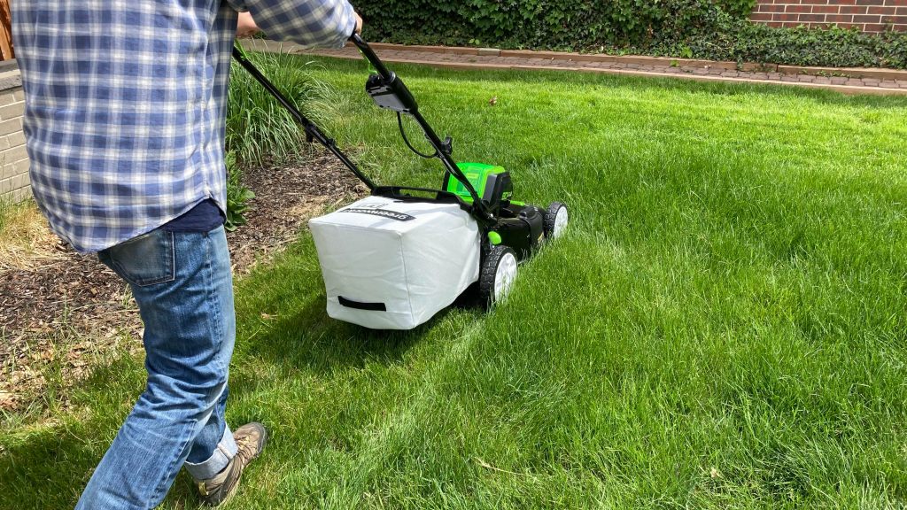
This electric lawn mower has been designed to work with small residential spaces. It is light in weigh, making it is easy for maneuver. It is perfect for all the tight yards and the intricated gardens. Perfect in delivering a hassle free lawn mower, you need no heavy machinery.

Recommended e-Axle: 250W Permanent Magnet Transaxle

This mower works well with a 250-watt permanent magnet transaxle for efficiency. This combination will give you a robust power and efficiency, hence, this mower becoming perfect for the lawn with low to medium rate growth. This technology has a permanent magnet that offers a smooth operation at the same time reducing the energy consumption which means it is cost saving and friendly to the environment .

Small Residential Electric Lawn Mower

Medium Residential Electric Lawn Mower

Crafted for the needs of moderately sized yards, the medium residential electric lawn mower is a power-packed and precise solution to homeowners’ needs. Designed essentially, to provide the perfect cut, every time, minus the unnecessary expenditure of larger and more cumbersome equipment.

Recommended e-Axle: 500W High-Torque Transaxle

Boost your lawn-care regime with the 500-watt high-torque transaxle, the powerhouse electric motor that can allow you to mow your lawn with a tad bit more enthusiasm. It’s a transaxle that’s capable of grappling with the highly demanding requirements of a medium residential electric lawn mower, and the high-torque perspective sees that no matter how dense or demanding the grass, the ideal cut will not be compromised.

Large Residential Electric Lawn Mower

When it comes to sprawling estates and extensive gardens, only the most powerful equipment will do. The large residential electric lawn mower serves as an optimal choice, as its sturdy construction allows ensuring professional-grade support for vast lawns and complex landscapes.

Recommended e-Axle: 800W Permanent Magnet Brush Transaxle LD04B

An exceptional level of torque and power delivered by 800W permanent magnet brush transaxle LD04B serves as a rational option for a *lawn mower * willing to overcome the issues of vast properties.

Commercial Light-Duty Electric Lawn Mower

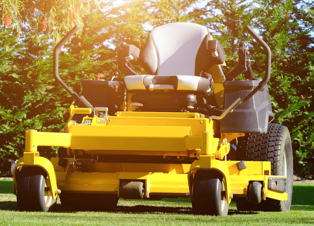
Designed to be equally at home in the varied settings of commercial landscapes, the commercial light-duty electric lawn mower is the ideal mower for public parks, school grounds and commercial properties. Its sturdy construction guarantees years of reliability and adherence to the requisite specification.

Recommended e -Axle: 1000W BLDC Transaxle ND42-1-43.9G

In the case of the commercial light-duty electric lawn mower, the ideal transaxle is the 1000W Brushless DC Transaxle ND42-1-43.9G . In an electric lawn mower designed for commercial use the value of its Brushless DC construction, with its high efficiency and durability, cannot be denied. 

Commercial Heavy-Duty Electric Lawn Mower

Keeping up with the demanding nature of commercial landscaping requires only the most robust and reliable equipment. As such, the commercial heavy-duty electric lawn mower was designed to specifically appeal to large-scale commercial applications with unmatched efficiency and durability.

Recommended e-Axle: 1300W Permanent Magnet Brush Transaxle LD04B

Looking for a mower capable of conquering even the most demanding lawn conditions, the 1300W permanent magnet brush transaxle LD04B seems like a perfect fit. With high-torque output, heavy grass, rough terrain, and long shifts are a thing of the past, guaranteeing your commercial property is always in perfect shape with no downtime.

What happens if you flip the magnets in a DC motor

Flipping magnets might decrease torque by up to 10%, as magnetic field alignment with the rotor becomes less optimal for power generation.

How DC Motors Work

Direct-current motors convert electrical energy into mechanical energy through the interaction of magnetic fields and electric currents. This process is guided by several fundamental principles and components, which together shape the DC motor’s operation, efficiency, and application in various fields.

Fleming’s Left-Hand Rule

Fleming’s Left-Hand Rule is vital to predicting the direction of force applied to the conductor in a magnetic field. This phenomenon is the foundation for the operation of any generator or motor. To ensure that the force is not pressed against the empty space, the designer must comply with this rule. The application of this rule is only necessary in motors where the direction of rotation control is paramount.

Magnetic Field and Current Interaction

The interplay of magnetic fields and electric currents is the primary requirement for the operation of DC motors. A magnetic field force is exerted on a wire loop that experiences the passing of an electric current. This invisible rotation is the motor’s output, which can drive machinery, wheels, or any mechanical system that requires movement. The speed and torque of the motor are also sensitive to the strength of the field and the amount of current inside the motor. Materials that offer strong fields while also being effective conductors are typically used for high-performance motors. The stator of such motors is often made of rare-earth magnets to produce the strong magnetic field, while the winding is made of copper .

Reversing DC Motors

Reversing the direction of a DC motor is a common requirement in many applications from automotive actuators to robotics. Understanding how to effectively reverse a DC motor, its implications for the motor’s longevity, and how it affects performance is vital to engineers and designers.

Identification of Motors with Built-in Directional Preference

Some DC motors are designed with a built in directional preference. This means that they are better suited or more efficient in one direction. This may be because of the construction of the commutator, how the brushes are conformed, or the field magnets are oriented. For example, a motor built for a power tool could be designed to run clockwise to match its operational requirements. Identifying these motors is important because the reduction in motor efficiency by reversing the direction can potentially be up to 5-10%, or the decrease in the effective torque it can output .

Longevity Concerns with Motor Direction

Reversing the direction of a DC motor can have implications for the longevity of a motor. Motors that change direction multiple times during their operational life could experience much greater wear on the brushes and commutator, greatly reducing their lifespan. For a motor fitted to run for 30,000 hours in one direction, it could potentially see a 20% reduction in lifespan when frequently reversed . This consideration will be vital to applications where maintenance access is limited, or if great longevity is important.

Performance Differences and Maintenance Implications

Reversing a DC motor can also affect its performance. A motor could output 10% more torque in one direction than the opposite. This must be considered when designing the device or machinery and their footprint, especially for applications with higher precision requirements.

A motor run in its non preferred direction may require far more maintenance, such as more frequent lubrication or brush changes and this may require a change in servicing from every 500 hours to every 400, and this is having a direct effect on the cost and downtime.

500W Encoder DC Brushless Motor

The 500W Encoder DC Brushless Motor excels in automation with high precision and power density. Its compact design, low noise, and all-copper build ensure efficiency and longevity. Ideal for unmanned vehicles and customizable applications, it offers stable, high-quality performance in various settings.

1.8KW Encoder DC Brushless Motor(With electromagnetic brake)

The 1.8KW Encoder DC Brushless Motor, equipped with an electromagnetic brake, offers high efficiency and precision in automation applications. It features a compact design, high power density, and advanced silicon steel core for improved torque. Ideal for unmanned vehicles and AGV systems, it ensures low noise, long service life, and robust performance. Its electromagnetic brake enhances safety and control, making it a versatile choice for various industrial needs.

 Reversing the Rotor Effects of Magnet Flipping

Reversing the rotor or flipping the DC motor’s magnets involves a process by which the motor’s magnetic field’s polarity is reversed. It directly affects the operation of the motor and impacts everything from how much torque it can generate to where the magnetic neutral plane of the rotor’s new polarity will lie. This information is thus essential to any application that requires the reversal of the motor’s direction or to any troubleshooting of motor that may require that reversal.

Polarity Inversion and its Immediate Post-Reversal Consequences

Polarity inversion achieved either by flipping the magnets in a DC motor or by reversing the current naturally results in the motor running in the opposite direction. The motor will quite possibly experience an almost immediate decrease in speed upon the current being reversed and the motor beginning to travel in the other direction. At a certain point, the motor’s speed will stop dropping, and it will remain between this and its original speed while it still moved in its proper direction. During this brief phase, the majority of motors’ efficiency worsens a few percent, with the most in-efficient dropping as much as 5% efficiency during the inversion phase. This decrease is caused and correlated to an imbalance in magnetic force in the motor.

Comparisons of Torque Generation

Afterwards, the torque that can be generated by the rotor of the motor may decrease when running in the opposite direction. This is since the rotor is designed to generate significantly more torque driving the correct direction. While spinning the correct way will enable the generation of 100 Nm of force, the manipulated flux presented when traveling in the wrong way will likely result in a maximum of 90 Nm being generated. If a specialized application requires the generation of more than 90 Nm, the motor’s direction cannot be reversed.

Advanced Commutator Role in Post-Reversal Magnetic Neutral Plane Alignment

The advanced commutator’s role in a high-end motor is to ensure that the magnetic neutral plane – the point where the coil in the armature is balanced and not magnetically inclined to one side – remains in the same position during operation. Perfect alignment is key to electrode brushes not sparking during operation and the ability for the motor to operate. The commutator can automatically correct any naturally tendency and ensure perfect alignment. By minimizing the need for perfect alignment, the component will allow the brushes to lasts longer and extend the operational life many times. The cost of implementation in a motor with the naturally shorter operational life has a cost of 15%-20% the overall cost of the motor.

DC Motor Varieties and Applications

DC motors are used in countless applications, ranging from small devices to large scale machinery. Their versatility is reinforced by the broad spectrum of appliances, provided by the availability of different types of DC motors, which can be used in the given context and depending on appropriate power, efficiency, and costs. Comprehending these types of DC motors and their range of applications allows balancing the performance- and cost-specific needs of a particular task.

Types of DC Motors

DC motors can be subdivided into brushed and brushless, the latter having subdivisions as well:

Brushed DC Motors: The most salient advantage of brushed DC motors is their simplicity and low cost. The broad spectrum of their applications spans across automotive items, consumer devices, and toys. On the other hand, this variety of appliances requires more maintenance due to brush wear and is generally less efficient. Power ranges of brushed DC motors span from a few watts in compact toys to multiple kilowatts from automotive DC motors . The cost varies across the sizes and applications of the motor. Correspondingly, a small motor designed for a toy can be purchased for as low as $1, while a high-output automotive DC motor will cost more than $50.

Brushless DC Motors : The varieties of BLDCs boast higher efficiency and lifecycle, as well as lower maintenance, not being equipped with brushes. As such, this variety is more preferable for more application, such as drones, electric vehicles, and high-end industrial purposes. Power ranges span across under 1 kW for low-output BLDC motors to over 150 kW for the latter’s variety. Correspondingly, they vary in cost, the simplest drones powered by a BLDC motor having under $10, whereas the engines for electric vehicles or industrial DC motors can cost over $1,000.

Applications of Reversible DC Motors

Reversible DC motors are used wherever bidirectional operation is required: in the realm of electric vehicles for mobility based on the ability to reverse, in automated machinery, in which motores have to spin in either direction to conduct the given task. The ability to reversed increases the scope of abilities, but also calls for them to be kept equally efficient and potent in any possible direction. For instance, electric vehicles are powered by BLDC motors, which require elaborate controls to regulate the direction and speed of motor operation and maintain optimal performance in either direction of motion.

Advantages and Disadvantages

Weighing the considered options, brushed DC motors have an advantage of very low initial cost and simplicity of control. Correspondingly, their disadvantages are lower efficiency and lifetime due to wear, and higher electronic intensity for control as compared with BLDC motors. The advantages of BLDC motors are efficiency, maintenance, lifespan, and ability to be run at high speeds with a better ability to moderate transition speeds and torque. The disadvantages are higher costs and more complex electronics.

Theorizing Magnetism beyond the Rotation

The topics and issues related to the study of magnetism in the context or along the axis of DC motors are one of the most fascinating looks at both the possible applications and technological innovations that further magnetism can undergo. While this is interesting in itself, the same phenomena and applications can be applied to comparing the two motors, the strength of two different magnetic fields or the same railway gun based on electromagnetism, the number of magnets, and external and internal magnetic fields, permanent magnets, and motor rotor’s role.

DC Motors vs Railway Guns

While DC motors are aimed to convert electric power to mechanical rotor’s rotation with a fairly common power range between several watts to a few kilowatts, railway guns’ purpose is completely and widely different. Railway guns use the same electromagnetic force to create linear movement of small metallic bodies with speeds going over Mach 6-7. That is achieved by applying the power comparable to several or a thousand megawatts for a couple of milliseconds. As such, a DC motor is much more efficient than a railway gun or performs better at creating electromagnetic force to propel current.

Single Magnet vs Multiple Magnets

Single magnet DC motors can often be seen in children’s toys or some older consumer goods, even current very cheap motor-based products will often use one magnet. However, multiple magnets will reduce the dead spots where the armature is held in place by the others’ force around it, effectively creating cogging effect, while also providing more magnetic force lines spread over the stator. This will create better performance in terms of torque and efficiency. These are often more expensive than single magnet alternatives even despite the brush const or the housing that comes with it, the difference being in magnets, which covers about half of all the cost, sometimes reaching over double or triple costs. As an example in the case scenario for a brushless DC motor, a rare earth motor magnet might cost from about $20 to over $100, which is equal or more than several cheaper DC motor overall price. Thus, it is worth considering alternate methods, such as a wound field motor, otherwise known as shunt wound motor.

How Does a Compact Hydraulic Power System Work and Its Benefits

Compact hydraulic power systems use pressurized fluid to transmit power efficiently in a small footprint, offering both energy savings and space efficiency.

Overview of Compact Hydraulic Power Systems


Compact hydraulic power systems are essential components in a wide array of machinery, offering the power needed in a space-efficient and effective manner. These systems utilize pressurized fluid to facilitate power transmission, allowing precise control over machinery movement and force across various applications, including industrial machinery and mobile equipment.

Definition and Components

A compact hydraulic power system is a comprehensive unit designed to convert electrical energy into hydraulic energy efficiently. The primary components include:

  • Hydraulic Pump: Converts mechanical to hydraulic energy, driving fluid through the system.
  • Hydraulic Fluid: The medium through which power is transmitted.
  • Reservoir: Stores the hydraulic fluid.
  • Actuators: Converts hydraulic energy into mechanical energy to perform tasks.
  • Valves: Directs the fluid’s flow and pressure.
  • Filters: Cleans the hydraulic fluid, ensuring efficient operation.

Each component significantly influences the system’s efficiency, durability, and performance.

Types of Compact Hydraulic Systems

The following table outlines various types of compact hydraulic systems, focusing on their key attributes without exceeding content limits:

TypePower RangeApplicationsEfficiencyCostLifespanAdvantagesDisadvantages
Standard Compact HydraulicUp to 100 kWIndustrial, automotiveHighModerate10-15 yearsVersatile, reliableRequires space
Miniature Hydraulic0.1-10 kWAerospace, medicalModerateHigh5-8 yearsCompact, preciseHigher cost, limited power
Mobile Hydraulic10-200 kWConstruction, vehiclesModerateVaried8-12 yearsDurable, mobileLower efficiency, higher maintenance

Working Principles of Compact Hydraulic Power Systems


Compact hydraulic power systems operate on the fundamental principles of fluid mechanics, converting mechanical power into hydraulic energy and then back into mechanical energy to perform work. The efficiency, reliability, and performance of these systems hinge on the proper functioning of their components and the hydraulic fluid’s role.

Basic Operation Process

The operation of a compact hydraulic power system begins with the hydraulic pump, which draws hydraulic fluid from the reservoir. This fluid is then pressurized and directed through valves to the hydraulic actuators, such as cylinders or motors. The pressurized fluid causes the actuator to move, performing work. After transmitting its energy, the fluid returns to the reservoir, ready to be cycled through the system again.

  • Power Range & Efficiency: Typically, these systems operate within a power range of 1 to 100 kW with an efficiency rating of 85% to 95%, depending on the system’s design and the quality of its components.
  • Cost & Lifespan: The initial cost can vary, but the investment in a high-quality system pays off with a lifespan of 10 to 15 years, significantly reducing long-term operational costs.

Role of Hydraulic Fluids in Power Transmission

Hydraulic fluid is the lifeblood of any hydraulic system, tasked with transmitting power, lubricating components, and carrying away heat. The choice of hydraulic fluid affects the system’s efficiency, speed, and temperature control.

  • Viscosity & Temperature Range: The ideal hydraulic fluid has a viscosity that allows for easy flow through the system but is thick enough to maintain a good seal between components. Most fluids are effective within a temperature range of -40°C to 100°C, ensuring reliable operation under various conditions.
  • Material Compatibility: Fluids must be compatible with the materials used in the system components, such as steel, aluminum, and rubber seals, to prevent corrosion or degradation.

Dc Brushless Hydraulic System

The CWHP Continuous Working System Brushless DC Hydraulic System, developed by Rotontek, operates powerfully in automotive and outdoor applications. Designed for continuous operation in diverse scenarios,

Electric Hydraulic

The EHC-6335500-16HC, a compact Electro-Hydraulic Actuator (EHA) from Rotontek, offers simplicity in installation without compromising power.

Maintenance and Care


Like any other transmission system, proper maintenance is essential for maximizing the lifespan and ensuring the reliability of Continuously Variable Transmissions (CVTs) and traditional automatic transmissions. CVTs and traditional Automatic Transmissions (ATs) call for regular care, though their specific maintenance needs might differ due to their distinct designs and operational mechanics.

CVT Maintenance

Routine Fluid Checks and Changes

Frequency: Check CVT fluid every 30,000 to 60,000 miles; however, the need to change the fluid will depend on how the vehicle is driven, vehicular make/model, and your manufacturer’s recommendations.

Importance: Belts and pulleys serve as the heart of a CVT’s operation, and these rely on a special fluid to ensure smooth operation. The use of an improper lubricant on a CVT can lead to severe damage or complete failure

Cost: The price of changing CVT fluid varies from $75 to $250, depending on the vehicle and service provider.

Belt and Pulley Inspection

Regularly checking the belt and pulley system within the CVT is crucial; wear on these components can affect operation and lead to complete transmission failure.

Inspection Interval: Every 40,000 miles, according to most manufacturers.

Software Updates

The CVTs of today are controlled by complex computer systems. Keeping these systems up to date can help improve performance as well as the longevity of the transmission.

Updates: Check for updates with your service record, or whenever the performance of the transmission is in question.

Automatic Transmission Maintenance

Fluid Replacement and Filter Change

Frequency: Check automatic transmission fluid (ATF) every 20,000 to 30,000 miles. Replace it every 60,000 to 100,000 miles, depending on your vehicle and transmission type.

Significance: Fresh ATF is essential for allowing the transmission’s internal components to move. It also cools and lubricates these parts for effective operation.

Cost: A full ATF change will cost between $100 and $300; this cost may increase if you also choose to change the transmission filter (if applicable) at the same time.

Linkage and Cable Adjustment

Properly adjusted connections allows for the timely and accurate transmission of power from the engine to the wheels.

Adjustment Interval: Adjust them when checking your vehicle’s fluids or if you notice any specific shifting issues.

Transmission Health Diagnostics

Having your transmission system checked frequently will allow you to catch any potential problems before they result in complete failure or professional service.

Key Features of Compact Hydraulic Power Systems


Compact hydraulic power systems are engineered to deliver high performance in a small footprint, making them ideal for applications where space is at a premium and efficiency is critical. These systems stand out for their efficiency and energy-saving capabilities as well as their compact design and effective space utilization.

Efficiency and Energy Saving

Compact hydraulic power systems are designed to maximize energy conversion and reduce waste, making them significantly more efficient than their larger counterparts. Efficiency levels can reach up to 85-95%, depending on the system’s design, the quality of components used, and the operational environment. This high efficiency translates into lower energy consumption, reducing operational costs for users.

Key factors contributing to their high efficiency include:

  • Advanced pump and motor designs: These are optimized for minimal energy loss.
  • Hydraulic fluid properties: Specially formulated fluids reduce friction and wear, further enhancing efficiency.
  • Precise control systems: Enable optimal system performance, adjusting power output to match demand.

Energy-saving benefits are not only seen in reduced electricity consumption but also in the lower heat generation, which diminishes the need for cooling systems, thus conserving additional energy.

Compact Design and Space Utilization

The compact design of these systems is another pivotal feature, allowing them to fit into tight spaces where traditional hydraulic systems cannot. Dimensions vary based on the system’s power capacity but are significantly smaller than those of standard hydraulic systems. For instance, a compact system designed for mobile applications might measure just 30x30x50 cm, a size reduction that can be crucial for integration into existing machinery without compromising performance.

Materials used in these systems, such as high-strength steel and aluminum, contribute to the system’s durability while maintaining a lightweight profile. This material selection, coupled with innovative engineering designs, ensures that compact hydraulic power systems do not sacrifice power for size, offering impressive lifespans that range from 10 to 15 years, depending on the application and maintenance.

Key advantages of the compact design include:

  • Better space utilization: Maximizes the available space within machinery or installations.
  • Increased flexibility: Offers more options for system placement, facilitating easier integration into various applications.
  • Reduced material usage: Lessens the environmental impact by using fewer resources in production.


Benefits of Using Compact Hydraulic Power Systems


Compact hydraulic power systems bring a myriad of benefits to industrial and mobile applications, ranging from enhancing machine lifespan and reliability to offering significant environmental advantages. These benefits are derived from the systems’ innovative design, efficiency, and advanced technology.

Increased Machine Lifespan and Reliability

The use of compact hydraulic power systems contributes to longer machinery lifespans and greater reliability due to several key factors:

  • Advanced manufacturing materials: Components made from high-quality materials such as high-strength steel and aluminum resist wear and corrosion, extending the system’s operational life.
  • Efficient design: Minimizes stress on moving parts, reducing wear and tear.
  • Precision control: Allows for smoother operation, decreasing the likelihood of mechanical failures.

Key points that highlight the impact on lifespan and reliability include:

  • Systems designed with a focus on minimizing leakage and protecting components can extend operational lifespan by up to 20%.
  • Regular maintenance intervals can be significantly extended, often resulting in 30-50% fewer shutdowns for repairs or overhauls.

Environmental Advantages

Compact hydraulic power systems not only enhance performance and reliability but also offer notable environmental benefits:

  • Reduced energy consumption: High efficiency translates into lower power usage, significantly cutting carbon emissions.
  • Less hydraulic fluid required: The compact nature of these systems means they need less fluid to operate, which reduces the potential for environmental contamination due to leaks or spills.
  • Smaller carbon footprint: The manufacturing process, requiring fewer materials, coupled with the system’s long lifespan, results in a reduced overall carbon footprint.

Maintenance and Troubleshooting

Maintaining and troubleshooting compact hydraulic power systems are essential to ensuring their longevity, reliability, and efficiency. Proper maintenance practices can significantly reduce the likelihood of system failures, while effective troubleshooting can quickly address any issues that arise, minimizing downtime and repair costs.

Routine Maintenance Practices

Routine maintenance is critical to the smooth operation of compact hydraulic power systems. Key practices include:

  • Regular inspections: Conduct thorough inspections of the hydraulic system components for signs of wear, leakage, or damage at least every 500 hours of operation.
  • Fluid management: Check hydraulic fluid levels and quality regularly. Change the fluid and filters according to the manufacturer’s recommendations, typically every 1000 to 2000 hours of operation, to prevent contamination and degradation, which can significantly affect system performance and lifespan.
  • Cleanliness: Keep the hydraulic system and its components clean. Contamination is a leading cause of hydraulic system failure.
  • Leak detection: Periodically check for leaks in hoses, fittings, and seals. Even small leaks can lead to significant fluid loss and contamination over time.

Implementing these maintenance practices can extend the system’s lifespan by up to 50%, ensuring cost savings on repairs and replacements and maintaining optimal efficiency.

Best DC Brushless Motor for 2024

Best DC Brushless Motor for 2024

The best DC brushless motor for 2024 combines high efficiency, durability, and advanced control features, ideal for diverse applications from automation to electric vehicles.

Best DC Brushless Motor for 2024

How to Determine the Quality of DC Brushless Motors

To determine the quality of DC brushless motors, focus on these essential factors:

  1. Efficiency: Quality motors have high efficiency, converting more electrical energy to mechanical power with less waste.

  2. Torque & Speed: Look for consistent torque across a range of speeds, indicating a versatile and reliable motor.

  3. Durability & Materials: High-grade materials and design signify a durable motor that withstands operational stress.

  4. Temperature Resistance: Good motors efficiently operate over a wide temperature range, avoiding overheating issues.

  5. Noise & Vibration: Lower levels suggest precise engineering, indicating higher quality.

  6. Brand Reputation & Reviews: Reliable brands and positive user reviews often reflect motor quality and performance.

  7. Certifications: Motors meeting industry standards and certifications have passed performance and safety tests.

Evaluating these criteria will help you identify high-quality DC brushless motors suitable for your needs.

Top DC Brushless Motor Brands and Models

In the realm of DC brushless motors, several brands stand out for their performance, efficiency, and compact designs.  These motors are highly suitable for a variety of applications. Here’s a comparison table highlighting top brands and models, with a special focus on Rotontek:

Rotontek‘s DC MOTOR Serie excels in offering superior performance and efficiency in a compact design, ideal for applications needing efficient motion in limited space. It’s the preferred option for small to medium-sized floor washing machines, electric trolleys, amusement vehicles, and dollies.

DC Brushless Motors Recommendation

In 2024, DC brushless motors enhance efficiency and performance across industries. Rotontek’s 500W-1.8KW motors stand out, offering superior compactness and power for diverse applications, making them a leading choice for innovative solutions.

500W Encoder DC Brushless Motor

500W Encoder DC Brushless Motor

The 500W Encoder DC Brushless Motor combines precision, power, and efficiency in a compact, quiet, durable design, ideal for unmanned vehicles.

800W DC Brushless Motor

800W DC Brushless Motor

The 800W DC Brushless Motor is efficient, quiet, and durable, perfect for automation, floor washers, and electric vehicles.

800W DC Brushless Motor(With electromagnetic brake)

800W DC Brushless Motor(With electromagnetic brake)

The 800W Motor with electromagnetic brake combines efficiency, quiet operation, and durability, perfect for electric trolleys and amusement vehicles.

1KW Encoder DC Brushless Motor

1KW Encoder DC Brushless Motor

The 1KW Encoder Motor boasts efficiency, precision, and durability, ideal for unmanned vehicles and industrial automation.

1.8KW Encoder DC Brushless Motor

1.8KW Encoder DC Brushless Motor

The 1.8KW Encoder Motor offers precision, efficiency, and durability, perfect for AGVs and unmanned vehicles in diverse applications.

1.8KW Encoder DC Brushless Motor(With electromagnetic brake)

1.8KW Encoder DC Brushless Motor(With electromagnetic brake)

The 1.8KW Motor with brake ensures efficient, precise, and safe operation for AGVs and unmanned vehicles, featuring advanced torque and durability.

Successful Applications of DC Brushless Motors

DC brushless motors have significantly impacted various sectors with their efficiency and performance. Here’s a concise overview of their successful applications:

  1. Electric Vehicles (EVs): Used for their efficiency and power, enhancing EV performance and range, exemplified by Tesla’s models.

  2. Drones and Aerospace: Provide precise, reliable propulsion in drones and are used in extreme conditions, such as NASA’s Mars Helicopter Ingenuity.

  3. Medical Devices: Power handheld surgical tools and ventilators, offering precision, minimal vibration, and reliability.

  4. Industrial Automation: Enhance productivity in robotics, conveyor systems, and CNC machines through precise control and efficiency.

  5. Consumer Electronics: Improve efficiency and battery life in products like vacuum cleaners and electric bicycles.

These applications highlight the versatility and transformative impact of DC brushless motors across industries.

Feedback From The Most Popular DC Brushless Motors

Feedback on Rotontek’s 500W-1.8KW DC brushless motors highlights several key points:

  • High Efficiency: Users commend the motors for their energy efficiency, resulting in lower electricity costs and enhanced battery life for battery-powered applications.

  • Robust Performance: The motors are praised for their strong and consistent performance across a range of applications, including industrial machinery and electric vehicles.

  • Reliability: Customers highlight the reliability and durability of Rotontek motors, noting their long service life with minimal maintenance required.

  • Compact Design: The compact form factor of these motors is appreciated for allowing their integration into tight spaces without sacrificing power or efficiency.

Overall, Rotontek’s 500W-1.8KW DC brushless motors are well-regarded for their quality, efficiency, and versatility in various applications.

The Best Hydraulic Power Unit in 2024

The top Hydraulic Power Unit in 2024

The best Hydraulic Power Unit in 2024 combines cutting-edge efficiency, robust construction, and smart technology, offering unparalleled reliability and adaptability for a wide range of applications, ensuring top performance in demanding environments.

The top Hydraulic Power Unit in 2024

Top hydraulic power units are engineered for high efficiency and reliability, meeting diverse industrial needs. Their compact design saves space while delivering essential hydraulic force for lifting and pressing operations.

Featuring pre-installed motors, pumps, reservoirs, and pressure relief valves, they ensure optimal performance and longevity. Easy to install and maintain, these units are suitable for both mobile and stationary applications, enhancing hydraulic system efficiency.

Working principle of Hydraulic Power Units

Hydraulic Power Units (HPUs) operate on Pascal’s law, distributing pressure uniformly in confined fluids. Here’s a brief overview:

  • Motor: Powers the pump, converting mechanical energy to hydraulic.
  • Pump: Pressurizes hydraulic fluid.
  • Reservoir: Stores hydraulic oil.
  • Valves: Control flow direction.
  • Actuators: Convert hydraulic pressure to mechanical energy for tasks.
  • Return Path: Fluid cycles back to the reservoir for reuse.

HPUs are closed-loop systems, with fluid continuously recycled. Valves regulate the process, enabling precise force manipulation.

Working principle of Hydraulic Power Units

Common Uses of Hydraulic Power Units

Hydraulic Power Units (HPUs) are widely used across various industries due to their ability to produce large amounts of power through small, flexible hoses and tubes. Here are some common uses:

  1. Manufacturing: HPUs are integral in the operation of machinery used in manufacturing processes, such as presses, conveyors, and plastic injection molding machines.

  2. Construction: They power heavy construction equipment like excavators, bulldozers, and cranes that require substantial force to dig, lift, and move materials.

  3. Aerospace: In the aerospace industry, HPUs are used for maintenance equipment, including the actuators that control the movement of aircraft components.

  4. Agriculture: Farming equipment such as tractors and harvesters use HPUs to perform tasks that require robust and sustained force.

  5. Marine: HPUs drive the steering mechanisms and control surfaces of many ships and also operate watertight doors and stabilization systems.

  6. Mining: HPUs are crucial in mining operations, powering drills, lifts, and other equipment in both underground and surface mining.

  7. Waste Management: Hydraulic systems are used in garbage trucks and recycling equipment to compact waste materials.

Hydraulic Power Units are appreciated for their reliability, efficiency, and ability to exert a high force relative to their size, which makes them suitable for a broad range of applications requiring motion control.

Advanced Control Systems for Hydraulic Power Units

Advanced control systems for Hydraulic Power Units (HPUs) significantly enhance the functionality and efficiency of these units. These control systems employ sophisticated technology to manage and monitor hydraulic flow and pressure, ensuring optimal performance of the HPU. They can be programmed for precision control, allowing for automation of complex tasks and providing feedback for system adjustments. Features often include programmable logic controllers (PLCs), sensors for real-time data, and interfaces for human-machine interaction.

Advanced control systems can improve the safety, reliability, and energy efficiency of HPUs. They can also facilitate predictive maintenance by analyzing data trends and detecting anomalies that indicate potential issues.

Below is a comparison table highlighting the differences between compact Hydraulic Power Units and other (standard) Hydraulic Power Units:

Compact HPUs are usually the go-to choice for applications where space is at a premium or where the hydraulic power demands are lower. Standard HPUs, on the other hand, are more suited for industrial settings where higher power and more robust systems are required. The choice between the two will depend on the specific needs of the application, including space, power requirements, and budget.

Calculating Power and Pressure for Hydraulic Units

Calculating power and pressure for hydraulic units is key to their design and operation.

  • Pressure (P) is calculated as force (F) divided by the area (A) the force is applied to, expressed as P= F/A.
  • Power (Pw) needed by a hydraulic pump is the product of the flow rate (Q) and pressure (P), divided by the efficiency (η) of the pump, given by Pw= Q×P/η.

For those seeking high-quality, reliable hydraulic power units that align with calculated specifications, we recommend exploring our range of products. Our hydraulic power units are designed for efficiency, reliability, and versatility, catering to a wide range of industrial applications.

119D Forklift Hydraulic Power Unit

30% longer operation, all-aluminum tank for heat dissipation, high-power motor, low noise, reduced consumption.

170 series hydraulic unit

1.5-2.2kW motor, 1.2-2.7cc/rev flow, high-pressure gear pump, versatile for various applications.

170A series hydraulic power unit

1.5-2.2kW power, 1.2-2.7cc/rev flow, automatic pump, and integrated valves, suitable for ships, trailers, and auto hoists, with a 30s/3min cycle.

119 Hydraulic power unit

0.8-1.2KW power, 0.5-1.0 cc/rev flows, for intermittent systems, supports manual operation, and is ideal for mini forklifts, RVs, and more.

109 B series Compact hydraulic power unit

Offers a compact design with a DC motor, gear pump, and valves, ensuring load maintenance and zero leakage, suitable for unidirectional and bidirectional systems.

Selecting the Right Hydraulic Power Unit

When choosing a Hydraulic Power Unit (HPU), consider:

  • Power Capacity: Assess the system’s required operational pressure and flow rate.
  • Size and Portability: Evaluate available space and mobility needs.
  • Fluid Type: Confirm compatibility with your hydraulic fluid.
  • Reservoir Volume: Match fluid volume needs, allowing for thermal expansion.
  • Pump Type: Choose (gear, vane, piston) based on efficiency and noise.
  • Control Options: Opt for manual or automated controls for precision.
  • Heat Dissipation: Plan for managing heat with coolers or exchangers.

Consult a specialist or manufacturer guidelines to ensure the HPU meets your system’s specifications.